Click on the pic to open a larger view in a new window. Clicking on the new image should zoom in close enough to get sufficient detail.
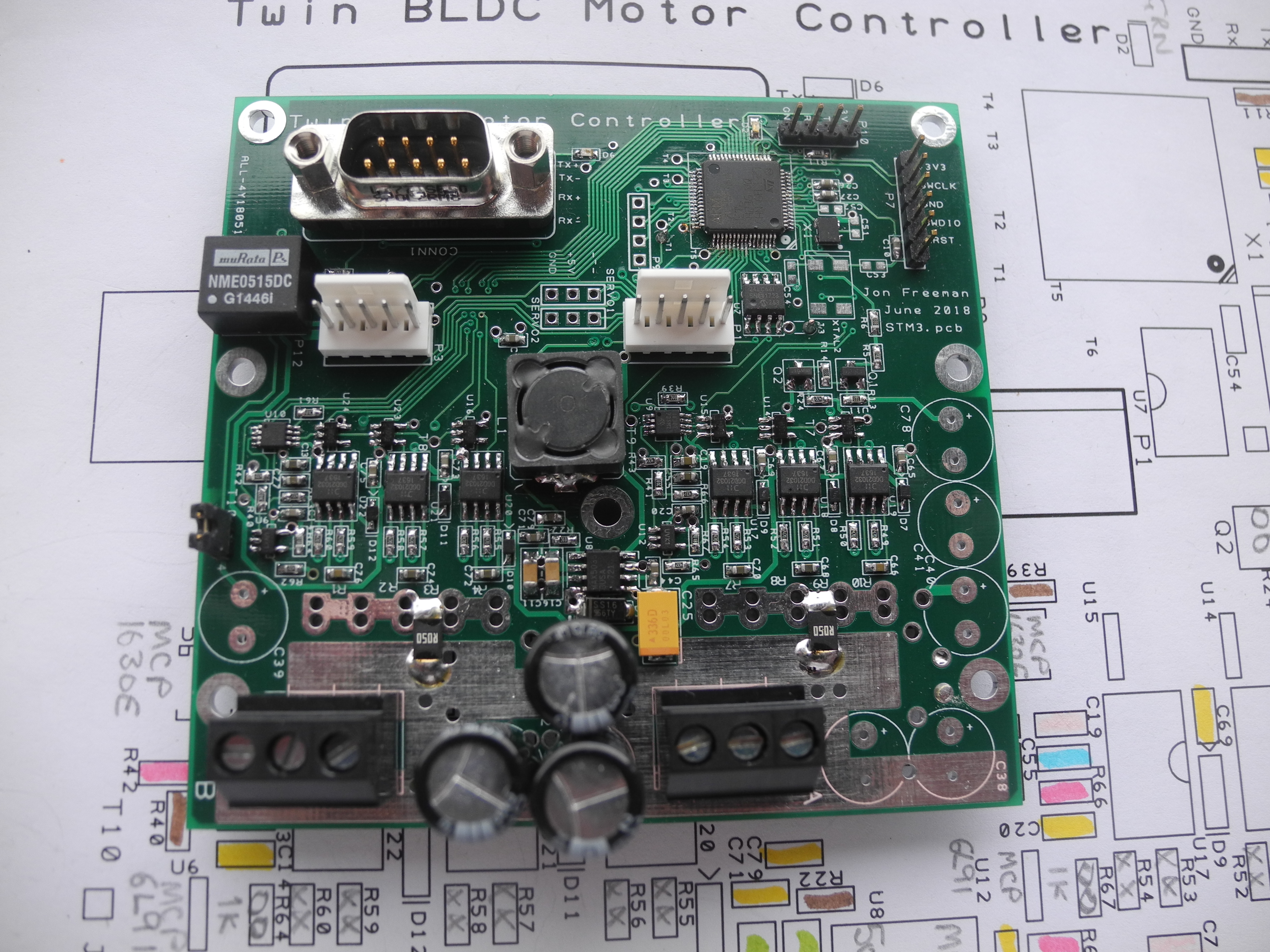
A look at the board
The board requires a DC supply within the range 11 to 60 volts. Power leads, missing in this image, are normally pairs of heavy red (+ positive) and black (- negative) wires soldered directly to the board and heading down at the bottom of the pic. Pairs are used just to spread paths of potentially heavy currents. The power leads may be permanently connected to a battery or other power source. When the unit is switched off, the leakage current is negligible (very few micro amps), but it is good practice to include a breaker.
Powering Up
The unit can be powered up in two ways; See the 2 pin jumper close to the left edge just above the missing C39. When fitted the board powers up with power applied to the power leads. An on/off switch could be connected here. The second way is through a connection from the 9 pin 'D' connector, see schematic for detail.
The pair of 3 way screw terminals are motor power connections, motor B on the left. Above, near the board centre, see pair of 5 pin header connectors. These connect the motor Hall sensors. The connection order of the three Hall sensor signals is important, as is the connection order of the motor power cables. Connection details for 'known' motors will be included here when I've got time, in the mean time proceed as follows.
Motor Hall Sensor Connections
Connect Hall sensor wires to 5 pin Molex connector observing correct connection of power and ground pins (see shematic), then unless you know better, take pot luck on which Hall sensor connection goes to which sensor input pin.
For motor power connections, there are six permutations, one of which will be 'correct'. This can be found by setting the board to a low voltage, low current output, and experimenting 'til you get it right, but please, power down before doing anything with motor power wires!
Setting the Correct Current for your motor
Just above the motor power terminals there is shown a single 'current sense' resistor for each motor, identified 'R050'. There is room to fit up to four per motor, soldering on more R050 resistors increases the motor drive current capability, about 10 amps peak per resistor, so, for example, motors taking maximum peak currents of 20 amps should have two R050 resistors fitted per motor. It is also possible to limit motor current through the setup firmware but please, don't be tempted to fit more resistors than you need as it reduces the 'dynamic range' of the current sensing circuits (spare R050 resistors supplied with boards).
Motor Drive Command Sources
The board responds to input signals from one (or more) of four sources;
Serial port (115200 baud 8N1) on connector P10 (top edge to the right)
Opto isolated serial port (19200 baud 8N1) on CONN1 'D' connector
Direction switch and speed potentiometer via CONN1
Radio control (via interface boards, fitted on request only)
The serial port on P10 was designed to be used for setup and test only. However, a number of users have chosen to use this as their principal command highway. No problem with this, but because it was not intended for general 'user' use, there is no protection on these raw CPU pins, careless use may easily result in destroying your board.
Use of an external interface is essential if using this port. An RS232-USB breakout interface (CP2104 or similar), connected between the STM3_EMC P10 serial port and your terminal or pc, or better still use a Bluetooth module. On Windows machines 'PuTTY' is suitable, there are others also.
WARNING! Use Bluetooth Adaptor
** PLEASE NOTE ** Port P10 directly connects to the raw port pins of the CPU. As such there is * NO * protection against spurious voltages, we advise connecting via a 3.3v Bluetooth or similar module which can be powered from the board. The opto isolated port available on CONN1 is for safe general use in power environments. If you need the higher speed of port P10, you should make arrangements to galvanically isolate port P10.
Hardware Considerations - Mounting
When driving motors heat is dissipated in the MOSFET modules on the rear of the board. For this reason the board should be mounted on a metal heatsink with the board supported on 5mm long metal pillars and screws using all seven mounting holes. Heatsink compound should be used to ensure good thermal flow from modules to heatsink. The degree of heating depends upon your useage, but as a first guess, assume one watt in heat per motor amp (reality almost certainly much less than this).
It is your responsibility to ensure sufficient cooling! The module should also be protected from ingress of all extraneous matter.
What's new in code Ver 3.1 - September 2021
This year has seen a catch-up on all the 'wants', with numerous small changes and additions including all customer requests. Version 3.1 is the stable release code, no further development is planned in the near future. Main features : -
Automated analogue data acquisition using Cortex DMA control hardware for faster, more accurate analogue reading with reduced software overhead.
Higher top speed - now 6% improvement
Better control at new lower minimum speed
Emergency STOP via serial command - (Possible future ESTOP input pin PC13)
Main forever-loop rate increased for shorter response times.
Software Watchdog settable to kill power if command stream from higher controller fails.
Auto Regen braking backoff attemps to prevent voltage rise beyond safe limit.
Added stepper motor driver. This is available when servo outputs are disabled, STEP and DIR outputs on servo output pins.
Housekeeping tidies as per... Ver 3.1 September 2021 binary here.
Includes low voltage tailoff, see 'us36'. As supplied for 18100 turbine project - Ver 3.2 September 2022 binary here.
What was new in code Ver 2.0.0
The move up from 1.x.x is all about migrating from the Mbed OS2 online compiler, to OS6.9 using Mbed Studio as advised by ARM Mbed. Some commands tidied and improved.
Ver 2.0.2 added 31st May 2021. Added one extra 'user setting', us31. This allows adjustment of driver's pot voltage FSD in the range 2.0 to 4.3 volt in 100mv steps. e.g.
us31 35[CR]
sets pot voltage range to 0 to 3.5
Firmware Updates - How To.
Six pin header P7 is for connection to an ST-Link device for use in software upgrades. When correctly connected, the pc 'looks through' the ST-Link and sees the CPU as external memory. Software upgrades are then similar to a 'file copy'.
A modified ST Nucleo board can be used as a flash programmer, see the How to programme STM32 Devices page for how to do this, and TAKE GREAT CARE to connect correctly.
Control Philosophy - Driving to Limits
It is possible to drive motors in tandem using a simple control potentiometer and Fwd/Rev switch. This might be good for basic traction applications, but takes little advantage of the advanced design philosophy.
In most serious applications one or more STM3 EMC boards will be driven through use of a higher level controller of some sort, issuing 'commands' affecting drive limits, to motors individually or in tandem. These commands are used for setting limits beyond which motors can not be driven. Variable limits in use are : -
Voltage limit
Current limit
Speed limit (MPH)
Revs per minute limit (RPM)
Motor behaviour then depends upon how you choose to set these limits.
Voltage limit
This restricts motor voltage as a proportion of supply voltage, 0 to 100%. Raising voltage raises speed.
When operating with moderate loads keeping motor current clear of the current limit setting, the motor speed can be varied by changing the voltage limit.
A popular choice for traction uses is to set the current limit high and to drive by varying this voltage limit. Actual motor speed will be affected by supply voltage and load torque, and may also be limited by the speed limit setting.
Current limit
Maximum potential motor current is limited by sense resistors and other settings to cater for motors of all ratings, tiny to huge. Within the maximum current so determined, the current limit restricts maximum motor current as a proportion, 0 to 100%. Raising current limit raises deliverable load torque.
Motors may be driven by setting the voltage limit high and using the variable current limit as a 'torque demand' control. For traction use, this gives a feel more similar to an engine throttle control.
You are free to use the voltage limit and current limit together in any combination. In general higher voltage limits result in higher speeds, higher current limits enable delivery of higher load torques.
Speed limit (MPH)
Set in 'user settings', useful limit of top road speed in vehicle use. Correct operation relies on other user settings equating shaft RPM with road miles per hour. Internally, the MPH setting is converted to RPM to work interactively with the 'Revs per minute' limit.
Revs per minute limit (RPM)
This provides for true 'speed control' in a stricter sense.
Setting the RPM limit to 'nnnn' RPM causes the motor to run at 'nnnn' RPM by using an inbuilt digital 'PID' controller. This maintains speed very close to the desired speed so long as none of the other limits are reached. Works in conjunction with the MPH speed limit where the lower of the two prevails. Speed will be below 'nnnn' RPM if the supply voltage or voltage limit is too low, and also when the load torque exceeds that deliverable with the current limit in force.
Controllable speed range depends upon factors including the motor and the characteristics of the mechanical system it drives. Bench tests using unloaded motors have seen good speed control from as low as 100 RPM up to over 6000 RPM. Fine tuning of the PID controller is possible.
As this is a digital control system the long term accuracy of speed setting is as good as the master system clock accuracy. This will be about as good as any digital watch. Over short intervals speed can be expected to fluctuate to a tiny extent as the control loop makes tiny discrete corrections many times per second.
Setting RPM limit is a popular option for applications including drills and machine tools.
To summarise
Motors run at the speeds they can attain within the constraints of mechanical load, and the speed limit, voltage limit and current limit as set. This gives choice and flexibility. For example you may choose to set the current limits to maximum and vary the speeds by changing the set voltage limit (this is what most simple motor 'controllers' do). You could also choose to set the voltage limits to maximum and achieve control by altering the current limit settings. This provides 'control by torque', which by itself is more suitable for some applications.
With total freedom to alter all the limits at will, you have a wealth of control possibilities at your disposal. Motor speeds are readable via serial port at any time, making it possible (easy?) for an external controller of some kind to supervise execution of whatever control algorithm you can dream up, or ask us to 'dream up' for you, at the most reasonable of rates.
This section has outlined methods for driving motors, in either direction. Motors may also be used as 'regenerative brakes' by command.
Basic Setup - Getting Started
It makes sense to complete basic setup before connecting motors, but...
With power applied to the STM3 EMC with the jumper fitted or On/Off switch 'On', you should see piercing blue light from an LED. This confirms logic low voltage supplies have powered up. You should also see a (not so piercing) green LED flashing rapidly, this confirms the system is running.
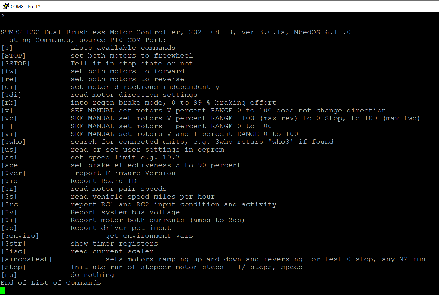
With your pc running PuTTY (or other terminal emulator) and connection established through P10, type a question mark and hit return. The board responds by outputting a list of commands it will respond to. For the remainder of this document we'll see examples such as
?v[CR]
This means type ?, type v, and hit return. This is the command asking for a power supply voltage reading, which should invoke a response similar to:
?v 23.8[CR]
This tells us the board is supplied at 23.8 volts.
We are using [CR] throughout to represent the single ASCII Carriage Return character, 13 decimal, 0x0D Hex.
Below the list of commands implemented in firmware ver 3.0.1a. Click image to open larger view in new window.
Commands List
This shows all commands accessible through the P10 serial port. A different set of commands, some similar and some not, are available through the open drain serial port on CONN1. These are not included here as those currently implemented are specific to one application (the Brushless Brutalist Loco). Clients have asked for their own set on this port, this we can easily do for you, and if simple enough, at no extra cost.
Command Descriptions
Commands Tidied in 3.0.x
New Uncluttered Commands!
Commands beginning '?' are 'query commands', asking STM3_EMC boards for some response.
Commands without the query prefix are for setting something. Examples :
"?v[CR]" requests report of system motor supply voltage, and could get the response
"?v 23.9[CR]"
"v75[CR]" sets motor voltage limit to 75%. Setting commands should not respond, although some do in case of error.
______
Board ID '0' to '9'
Any command may also have an optional single digit prefix (ahead of any '?'). This is useful in multi-EMC systems where some central controller is used.
Each STM3_EMC board has a user settable 'ID' as a single digit '0' to '9'. Responses can be supressed using a single digit prefix ahead of '?'. The EMC will only respond when the digit prefix matches its ID. This is used where multiple EMCs are ganged together using the opto isolated parallel command bus where a controller can broadcast commands for all EMCs to obey by omitting the '0' to '9'prefix, or commanding EMCs individually with the prefix.
Likewise, a digit prefix to query commands causes only the addressed unit to respond.
Oops !
Percentage! Throughout the following, reference is frequently made to entering parameter values as percentages in the range 0 to 99, this chosen rather than 100 simply to keep command lengths short. This does not, however, mean we are denying you the ability to reach full power, it would have been more succinct to use the term 'perninetynineage' throughout, but ... To the Commands.
Query Commands
Reading Speed Controller Info
?[CR]
?[CR] causes output of the Command List, similar to that shown above.
?id[CR]
Reports board '0' to '9' ID. Example response :
?id7[CR]
Used with ID prefix (e.g. '7?id[CR]') evokes response only from STM3_EMC with ID value '7'. This is useful in multi-EMC systems where a central controller may discover the identities of how ever many EMCs are connected by issuing '0?id[CR]', '1?id[CR]' to '9?id[CR], and noting which are responded to. (Note - small delay required between commands to allow for responses to complete without data crashes)
?ver[CR]
Returns current firmware version string
?q[CR]
A group of enquiries returning lists of information on motor performance. Typical response to q[CR] :-
?q6.35[CR]
reporting speed 6.35 MPH (averaged from both motors, assuming traction application).
?q1[CR]
Returns MPH as above and also DC supply voltage. Typical response
?q6.35 27.6[CR]
?q2[CR]
Returns three floating point values, adds reading of sum of motor currents to speed and voltage, example : -
?q6.35 27.6 10.35[CR]
?q3[CR]
Returns four floating point values, MPH, voltage, MotorA current, MotorB current. Example : -
?q6.35 27.6 5.15 5.20[CR]
?q4[CR]
Returns four floating point plus two integer values, MPH, MotorA current, MotorB current, MotorA RPM, MotorB RPM. Example : -
?q6.35 27.6 5.15 5.20 1127 1143[CR]
?r[CR]
Reports motor revs per minute. Return example:
?r 1250 1269[CR]
indicates MotorA at 1250 RPM, MotorB at 1269 RPM.
?s[CR]
Read vehicle speed MPH to 2 decimal places - depends on user settings for wheel size and gear ratio to be of any use.
?rc[CR]
Report condition and activity on the two radio control inputs (radio control not available on all boards).
?v[CR]
Report EMC supply voltage
?i[CR]
Read motor currents. Example response:
?i 10.26 8.37[CR]
informs MotorA drawing 10.26 amp, MotorB drawing 8.37 amp. NOTE these readings can not be accurate (good tech reasons) but may be useful approximations. Give or take a little, the sum of these two readings should be about what an ammeter in the EMC supply lead might read.
?p[CR]
Reports setting of driver's control potentiometer wired through CONN1. Range 0.000 to 1.000. Typical response :
?p 0.123[CR]
?isc[CR]
Read current scaler - see User Settings section for the full gen. A current scaling user setting allows for setting max motor currents to a percentage of that set by current sense resistors alone. This reads back the setting of 25% to 100% as floating point 0.250 to 1.000, e.g. response
?isc 1.000[CR]
?di[CR]
Request motor mode settings. responds:
MotA x, MotB y[CR]
where 'x' and 'y' are one of 'F' forward, 'R' reverse, 'B' in regenerative braking, or 'E' for error.
?STOP[CR]
Reports whether or not Emergency Stop state has been entered.
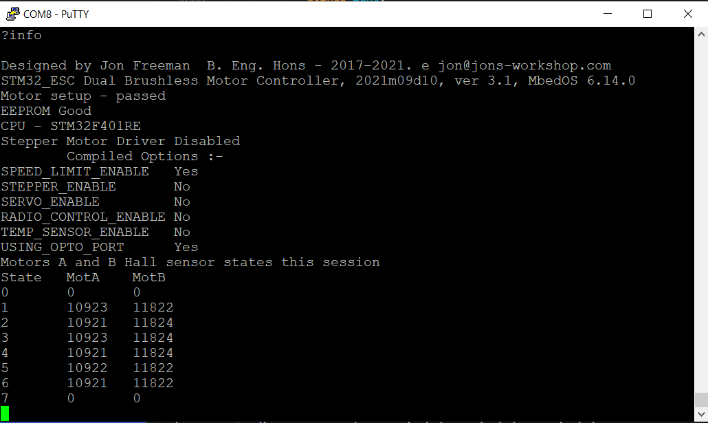
?info[CR]
Causes output of screen data below
System Information Screen
Click on image for clearer, enlarged window.
Shows version info and compile options selected when last compiled. Changing these requires re-compiling the source code having commented or uncommented the relevant #defines in header file STM3_ESC.h
Of value for fault finding systems, the lower part of the display shows Motors A and B Hall sensor states this session. Each motor has three Hall sensors, giving a 3 bit binary state code indicating rotor position. Six valid combinations exist for all possible combinations of one high two low, or two high one low, the valid Hall sensor state set. State 0 should never be seen, state 7 should only be seen when motor is disconnected.
When motors have run or are running, all valid states from 1 to 6 should be seen the same number of times, allowing for a max discrepancy of 2. Deviation from this would indicate hall sensor problems, or more likely, dodgy wiring or connectors.
______
Setting Commands
______
Safety
STOP[CR]
Emergency STOP. Sets motor voltage and current limits to 0. Green LED flashes slowly indicating ESTOP state.
Reset out of ESTOP state using
STOP-1 -1[CR]
Motors remain still until new voltage and current limits set.
watchdog[CR]
Enables and starts a firmware Watchdog Timer. Once started the timer is reloaded after each serial command received and executed. After about 2 seconds with no serial commands the watchdog times-out and puts EMC into Emergency STOP state. Issuing
watchdog-1[CR]
disables the watchdog, but leaves the EMC in the ESTOP state.
______
Direction Setting
fw[CR]
Sets MOTOR_FORWARD mode for both motors (direction may be swapped under User Settings). No response
re[CR]
Sets MOTOR_REVERSE mode for both motors (direction may be swapped under User Settings). No response.
di
Used for setting motor rotation direction independently, takes 0 or 2 parameters. No response.
di[CR] sets both motors in the 'Forward' sense, as does
di0 0[CR]
di 0 1[CR] sets MotorA forward, MotorB reverse.
di 1 0[CR] sets MotorA reverse, MotorB forward.
di 1 1[CR] sets both to reverse, as 're[CR]'.
NOTE use of 'fw', 're' or 'di' causing change in direction also sets affected motor power to zero (to avoid instantaneous reversal attempts). Rotation resumes after setting new voltage and current limits (see 'v', 'i' and 'vi')
______
Voltage and Current Setting
Motors are controlled using individually set voltage limits and current limits.
For simple speed control, one option is to set current limits high, varying voltage limits to alter speed.
For torque controlled applications, voltage limits may be set high, with torque controlled by varying current limits.
Providing access to both voltage and current limits makes this controller infinitely more versatile than almost any other on the market!
v, i and vi
These three commands are for setting motor voltage limits (v), current limits (i), or both together (vi), and accept parameter values in the range 0 to 99. Use 'v', 'i' and 'vi' when direction is set using 'fw', 're' or 'di'. See 'vb' for bidirectional motor driving.
v
Sets motor voltage limit as percentage - Uni-directional, range 0 to 99. No response
v45[CR]
sets motor voltage limit to 45% of supply voltage for both motors. Direction not affected. This may also take two parameters:
v 45 70[CR]
sets motor voltage limits to 45% for MotorA, and 70% for MotorB
v[CR] with no parameters, is equivalent to v 0[CR]
i
Sets motor current limit as percentage, range 0 to 99. Can set both motors the same using one parameter, or set individually using two. Examples:
i25[CR]
sets current limit on both motors to 25% of maximum.
i 25 50[CR]
sets MotorA current limit to 25%, and MotorB to 50%.
i[CR] with no parameters, is equivalent to i 0[CR]
vi
Takes zero, two or four parameters, sets both voltage and current limits for both motors.
vi 10 20[CR]
sets both motor voltage limits to 10% and both motor current limits to 20%
vi 10 20 30 40[CR]
sets MotorA V and I limits to 10% and 20% respectively, likewise for MotorB V and I limits to 30% and 40% respectively.
New in Version 3.0.x - vi[CR] (i.e. with no parameters) is a shorthand equivalent to
vi0 0[CR] or
vi 0 0 0 0[CR]
vb
Sets motor voltage limit as percentage - Bi-directional, range -99 to 99.
vb 45[CR]
sets motor voltage limit for both motors to 45% of supply voltage with motor running 'forward', whereas
vb-99
sets both motor voltage limits to full supply voltage and sets direction 'reverse'. This may also take two parameters:
vb -45 70[CR]
sets MotorA voltage limit to 45% with direction set to 'reverse', and MotorB voltage limit to 70% with direction 'forward'.
NOTE just because you can slam instantly between full forward and reverse does not make this a good idea!
r
Sets RPM limit the same or differently for both motors. e.g.
r1725[CR]
causes both motors to run at 1725 RPM provided this does not take the voltage limit beyond its setting at that moment, likewise does not cause motor current to rise beyond the present setting of current limit, and also does not cause speed to exceed the speed limit MPH.
r1725 2000[CR]
sets MotorA limit to 1725 RPM, and MotorB limit to 2000 RPM.
r[CR]
is equivalent to
r0[CR]
setting both to 0.
'r' Running speed too low ?
Motors will run at lower than RPM limit with mechanical overload, supply voltage too low, or other set limits reached.
'r' Running speed too high ?
If the motors are over-run, e.g. by vehicle running away down hill, the PID controller sets motor power to zero but does not activate brake!
p
d
'p' and 'd' allow adjustment of the 'P' proportional and 'D' differential coefficients of the PID controller. At powerup both default to 1.0
It is unwise to play with these unless you are familiar with use of PID controllers, but should you discover settings more suited to your system, you should include 'p' and/or 'd' commands in the setup script at startup. Example
p0.5[CR]
d2.5[CR]
sets 'P' to 0.5 times, and 'D' to 2.5 times factory default settings.
______
Braking
rb
Sets MOTOR_REGENBRAKE mode for both motors, and takes 1 parameter in range 0 to 99, representing braking effort percentage. e.g.
rb60[CR]
sets regen brake at 60%. No response.
sbe
Set brake effectiveness, range 0 to 99. Bit like brake pedal pressure. NOTE using regenerative braking may raise supply voltage above safe level. It is YOUR responsibility to clamp the supply rails to prevent over-voltage damage.
______
User Settings
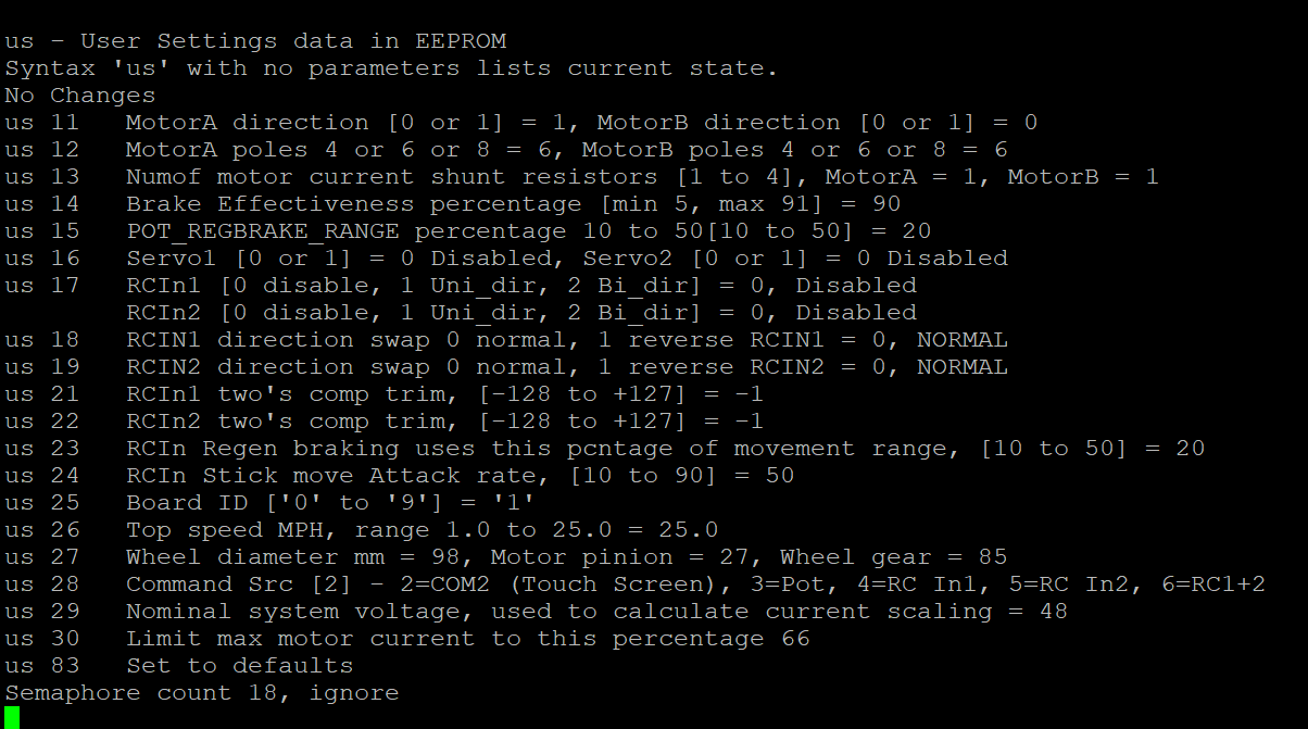
us
User Settings. This is the big one. Really big, but to take a look at how user settings have been set, issue a 'us' command with no following parameters :
us[CR]
This produces a list showing settings as they are. See separate section below for full gen on user settings.
______
Setting Speed Limit
ssl
A shorthand method to set speed limit.
ssl 10.75[CR]
sets speed limit to 10.75 MPH. Successful speed limit setting depends on several of the user settings being sensibly set.
Miscellaneous
sincostest
Run both motors driving the voltage limits in bi-directional mode using values from rapidly updated sin and cosine functions. Causes motors to speed up, slow down, stop, reverse, repeat. 90o phase shift means that one motor is at max speed as other passes through zero.
sincostest 1[CR]
enters test mode (where parameter shown as 1 could be any non zero). To exit test mode enter :
sincostest 0[CR] or
sincostest[CR]
Fun to watch, for about seven seconds.
step S V A[CR]
New Ver 3.x.x - Stepper motor driver. Uses servo outputs, therefore only available when both servos deselected.
'step' keyword followed by one or more numeric parameters:
First parameter 'S' is required, the number of steps to move, positive or negative determining direction.
Second param 'V' step rate, steps per second.
Third param 'A' acceleration used in starting and stopping, steps per second per second.
e.g. 'step -5000 800 2500[CR]' initiates move of 5000 steps in the '-' direction at a maximum of 800 steps per second, with speed ramped up and down at 2500 steps per sec per sec.
The STEP and DIR outputs drive an external stepper or servo motor controller. WARNING these are raw 3.3v microcontroller outputs that will not take abuse. External buffers advisable.
nu[CR]
null function, does nothing.
______
It's Not Here !
Other commands may appear in the command list. If the one you're looking for isn't described here, then it's to do with work in progress, broken, or only intended as machine-readable by other controllers.
Commands may be described above but not seen in the Command List shown using '?[CR]'. This page is intended to describe all commands for code compilations with all compilation options (Servo out, Stepper motor, Radio control, Temperature sensor) enabled. Your code may not have all enabled.
______
User Settings - How to, and why.
The 'us' command from above.
Typing in:
us[CR]
invokes sending the complete list of user settings as shown below (click on image for larger view in new window). This shows all settings values as are.
User Settings List
User settings are numbered, the numbers don't start at '1', and some numbers are missing. Space between 'us' and number optional, 'us11' and 'us 11' work the same ... here goes!
us 11
'us 11' is used to set default rotation directions by setting '0' or '1'. Two parameters are needed, one for each motor. Typing:
us 11 1 0[CR]
sets default rotations in opposite senses, MotorA '1', MotorB '0'. Which way corresponds to clockwise depends on how you have the motor and sensors wired.
us 12
Sets number of motor poles for motors individually, two parameters required. This is used in calculating motor speed RPM. Valid values are 4, 6 and 8.
us 12 8 8[CR]
would be used when two 8 pole motors are in use.
us 13
Current sense '0R05' resistors fitted for motors A and B
us 13 2 2[CR]
informs code two current sense resistors are fitted for each motor.
us 14
Braking effectiveness
us 15
Brake effort only when using control potentiometer
us 16
Servo output enables, 1 and 2
us 17
Radio control input enables 1 and 2
us 18
Radio control 1 input sense (direction). Use
us 18 0[CR] or us18 1[CR] to set desired sense
us 19
Radio control 2 input sense (direction), as above
us 21
Radio Control input 1 trim (-128 to +127)
us 22
Radio Control input 2 trim (-128 to +127)
us 23
RC stuff
us 24
RC stuff
us 25
Sets 'unique' board ID, '1' to '9'. This is useful where multiple STM3 EMC boards exist in a system using easy connect of the opto isolated, open drain serial link. Boards with different IDs can be addressed individually and receive broadcast commands.
us 26
Sets top speed limit, range 1.0 to 25.0 MPH.
us 27
Takes three parameters to set Wheel dia mm, Motor pinion teeth, Wheel gear teeth
us 28
Should only be set to 2 or 3 (without radio control inputs anyway). Analogue 'pot' input is enabled using 'us 28 3', disabled by 'us 28 2'.
us 29
Your statement of Nominal System Voltage, e.g.
us29 24[CR]
sets code for nominal 24v system.
us 30
Current limit scaling factor in range 5% to 100%, default 20%. e.g.
us30 66[CR]
sets max current limit to 66% of that determined by current sense resistors.
us 31
New in Ver 2.0.2
Sets voltage range for 'Driver's Pot' analogue input in range 2.0 to 4.3 volt e.g.
us31 35[CR]
sets 3.5 volt FSD.
us 36
Battery Saver - Minimum working voltage tailoff.
This allows setting of a minimum working voltage below which no power is delivered to the motors. Further, by specifying two voltages, you can define a voltage ramp over which motor power is scaled back. This is useful, for example, in battery powered systems where this feature can be used to prevent over-discharge. Useage :-
us36 22 24[CR]
This will lead to motor power being reduced a little for voltages slightly below 24V, with motor power reducing to zero once voltage falls to 22V. Parameters entered in either order. Entering the same value twice results in a voltage ramp of 1V above entered value.