Published in Engineering In Miniature magazine Oct, Nov, Dec 2015
By Jon Freeman B. Eng. Hons
This is the story of the design of a new battery electric locomotive in 5” gauge. Designing from scratch, the opportunity was taken to look into using some of the newer motor technologies available today. What follows concentrates on the design process, the thinking that went into each step of the way, rather than the more familiar sequential assembly constructional series. More of an emphasis on the “why” rather than the “how”, although there will be enough detail for the keen model engineer to use many of these ideas in their own projects. Along with the mechanical design, we venture into the electronics and control systems.
The Project – Why ?
My partner Julie and I are regular drivers on the Taunton Model Engineers miniature railway in a local park. "Rides for children of all ages", we often say to parents who, having let their kids climb aboard, wonder whether they should have a go as well. We drive our old 'Polly 1' steam loco which is well suited to the job, powerful enough, and will keep running all day with the minimum of fuss. However, keeping Polly in good enough condition to run as reliably as this involves spending quite some time in cleaning and routine maintenance. This is all well and good, but time spent servicing Polly is time spent not getting on with another steam project on the bench, a 4-6-0 that has been 'due for completion next year', for a couple of years now. The old idea was to end up with two steamers, either one of which in good running order being sufficient for reliable running in the park. The newer idea was to build a battery electric loco as a low-maintenance quickie, then more time could be freed to work on some of the unfinished projects in the workshop. Rationalising it in this way – start a new project to help finish off a number of already started projects – seemed to make sense at the time.
Design – The First Stages
The starting point of good design is in deciding what outcome you want, in this case in deciding what we wanted the finished loco to do – coming up with a specification. This boiled down to the beautifully brief : -
“A low-maintenance five inch gauge locomotive, capable of running for at least four hours in the park, hauling any load routinely encountered there.”
As we normally run with one passenger carriage and rarely with two, we decided a 'pulling power' that was 'not less than Polly' was required. Because wheel-slip is often a limiting factor when rails are wet or when pulling the heavier loads, it was similarly decided the finished weight should be 'not less than Polly'. Adherence to these should ensure we end up with a loco 'not less capable than Polly'.
To allow for occasional running on other tracks with tighter curves, wheel configurations such as 0-6-0 and 0-8-0 were ruled out, leaving a choice between 0-4-0 or some twin bogie design. Having a length of 4.5” diameter steel in stock long enough to slice up to make eight wheels settled it, a design using two four-wheeled bogies was settled upon.
Having looked at a number of other designs using single or multiple motors, we considered a design using one motor to drive each axle, four motors in total, a configuration which lends itself to a simpler, tidier layout.
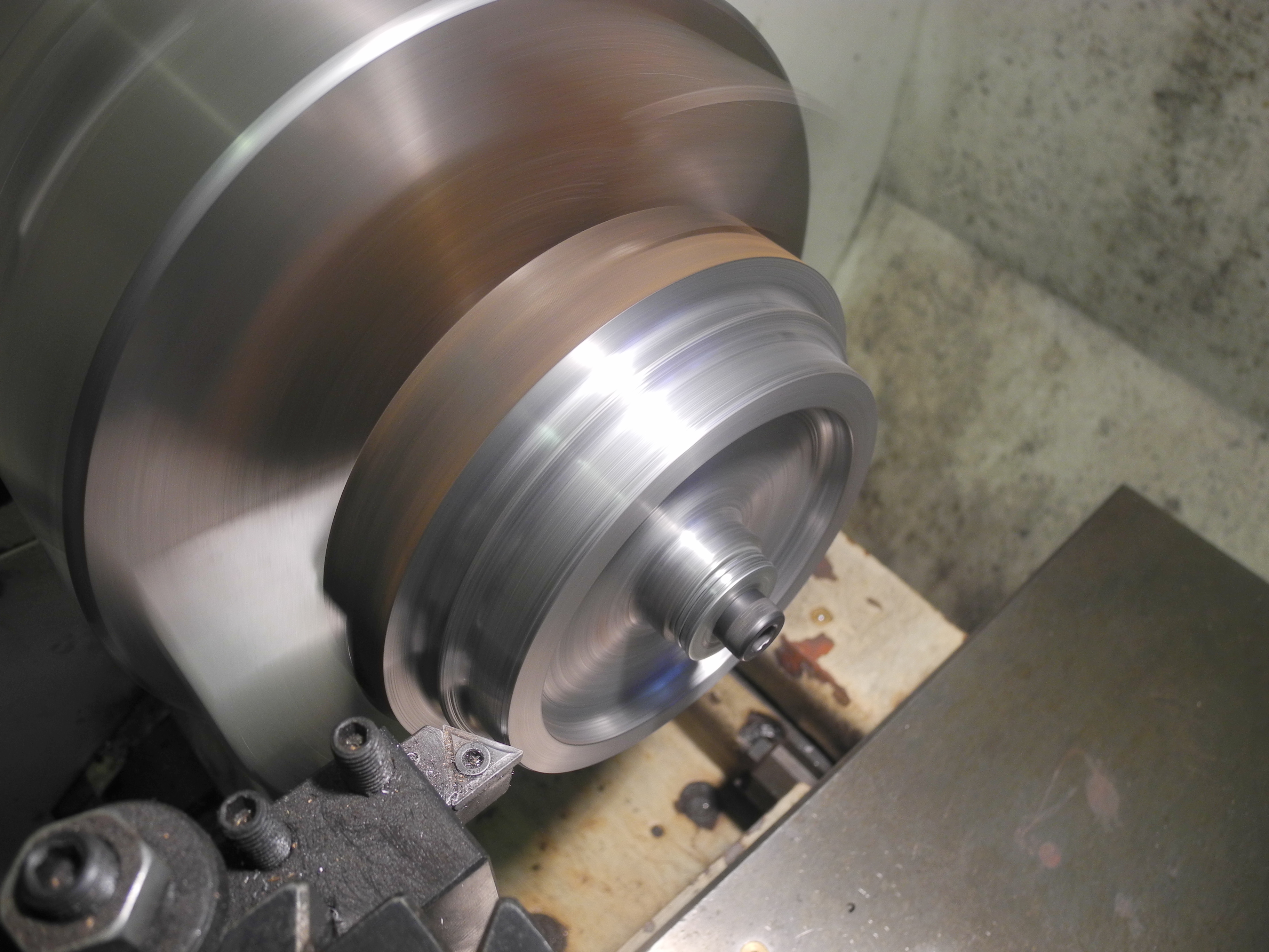
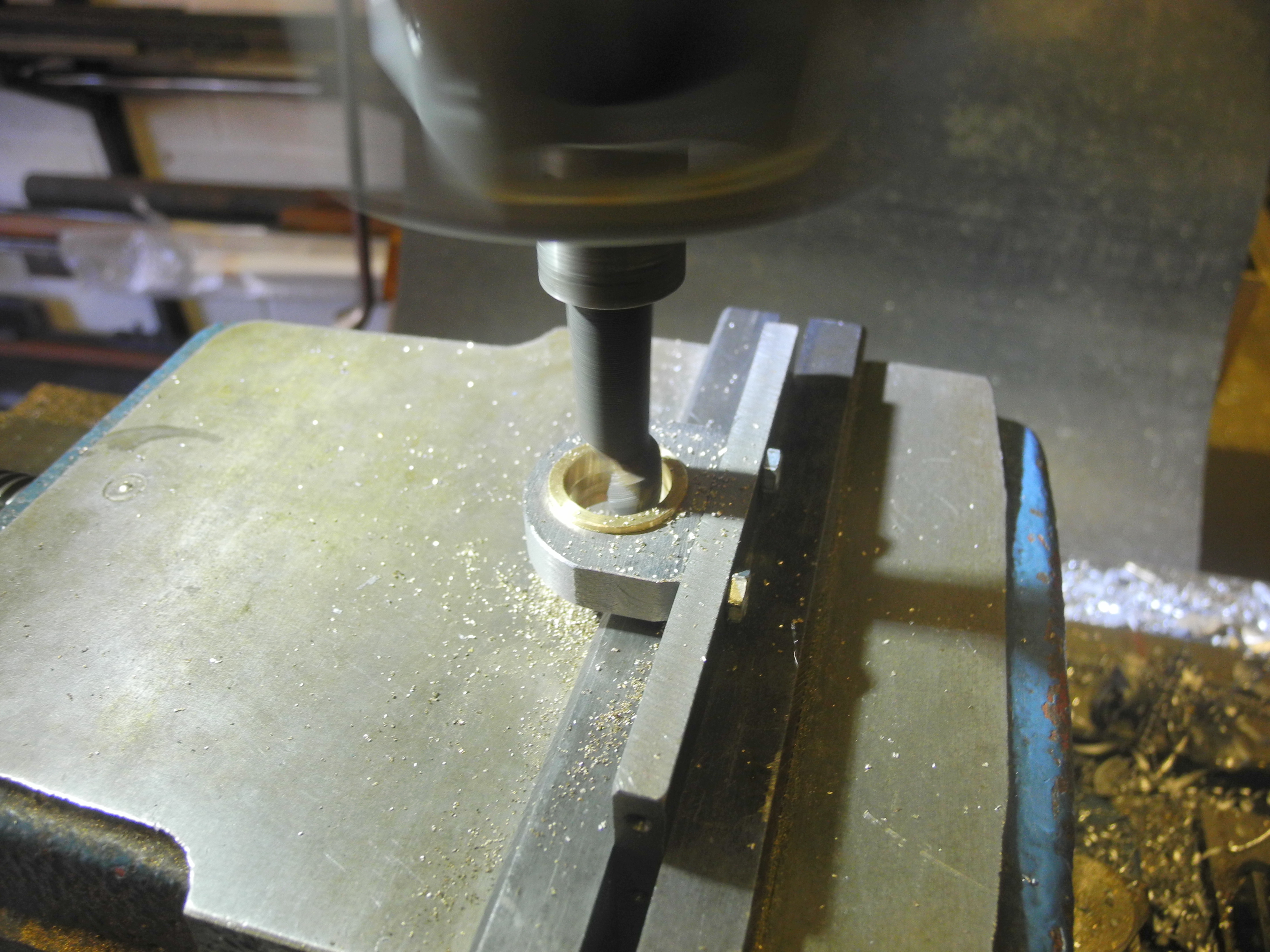
FIGURE 1 - ELECTRIC LOCOMOTIVE FIRST SKETCH Photograph 1 - Finishing a wheel.
FIGURE 3 - BOGIE ELEVATION
Figure 1 is not to scale, indicating a pair of bogies and some connecting chassis with dimensions to be determined. A search of the internet found web sites listing all the vital statistics of probably every diesel and electric loco to run on British rails. This gave some idea of wheel diameters and bogie wheelbases. Wheel dimensions were chosen at this point, the final decision on bogie wheelbase was deferred until motors were selected and an idea of how everything might fit was evident. The bogie centres dimension needs no thought at this early stage, this along with decisions on the finished appearance are for another day.
FIGURE 2 - BOGIE PLAN
A more rigorous design process would have seen the design complete and all drawings produced and checked before the cutting of any material. However, with the wheel dimensions decided upon and the material to hand, a set of eight wheels were machined and profiled (photograph 1), having first looked up the wheel profile standard from the Ground Level Five Inch Gauge Main Line Association web site (www.gl5.org).
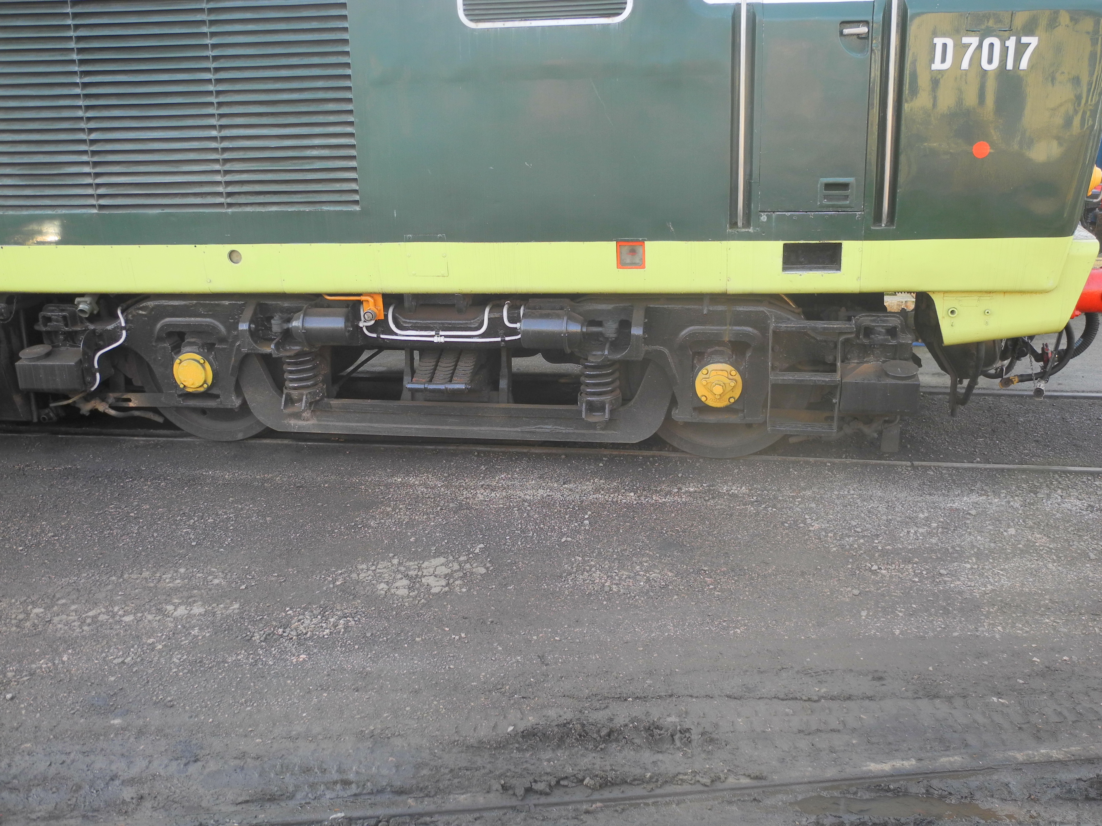
Photograph 2 - D7017 at Williton
Figure 2 is a simple plan view sketch of a bogie, drawn to help in planning how and where the motors might be fitted, how power could be transferred to the wheels, and how the suspension might be arranged. Outside frames were chosen to maximise space for the motors, drive and suspension components. The only dimensions shown are those that have been firmly decided at this stage in the design.
Thinking about suspension, inspiration was sought on a visit to the West Somerset Railway. A selection of diesel locomotives were seen, and the suspension arrangement on D7017 (photograph 2) seemed to make sense. The frames shown in the sketch plan of Figure 2 are far enough apart to allow space for some suspension girder with ends bearing on the top of the axle boxes, as with D7017.
Many loco designs use horn castings or fabrications to thicken the frames around the axle boxes to give a reasonable bearing surface area for the sides of the axle boxes. This is necessary with steam locos due to the large reciprocating forces transmitted through the piston rods and cranks, but such forces are absent in this case. Therefore, if the frames are made using some reasonably stout material, the added complication and expense of horn blocks may be dispensed with.
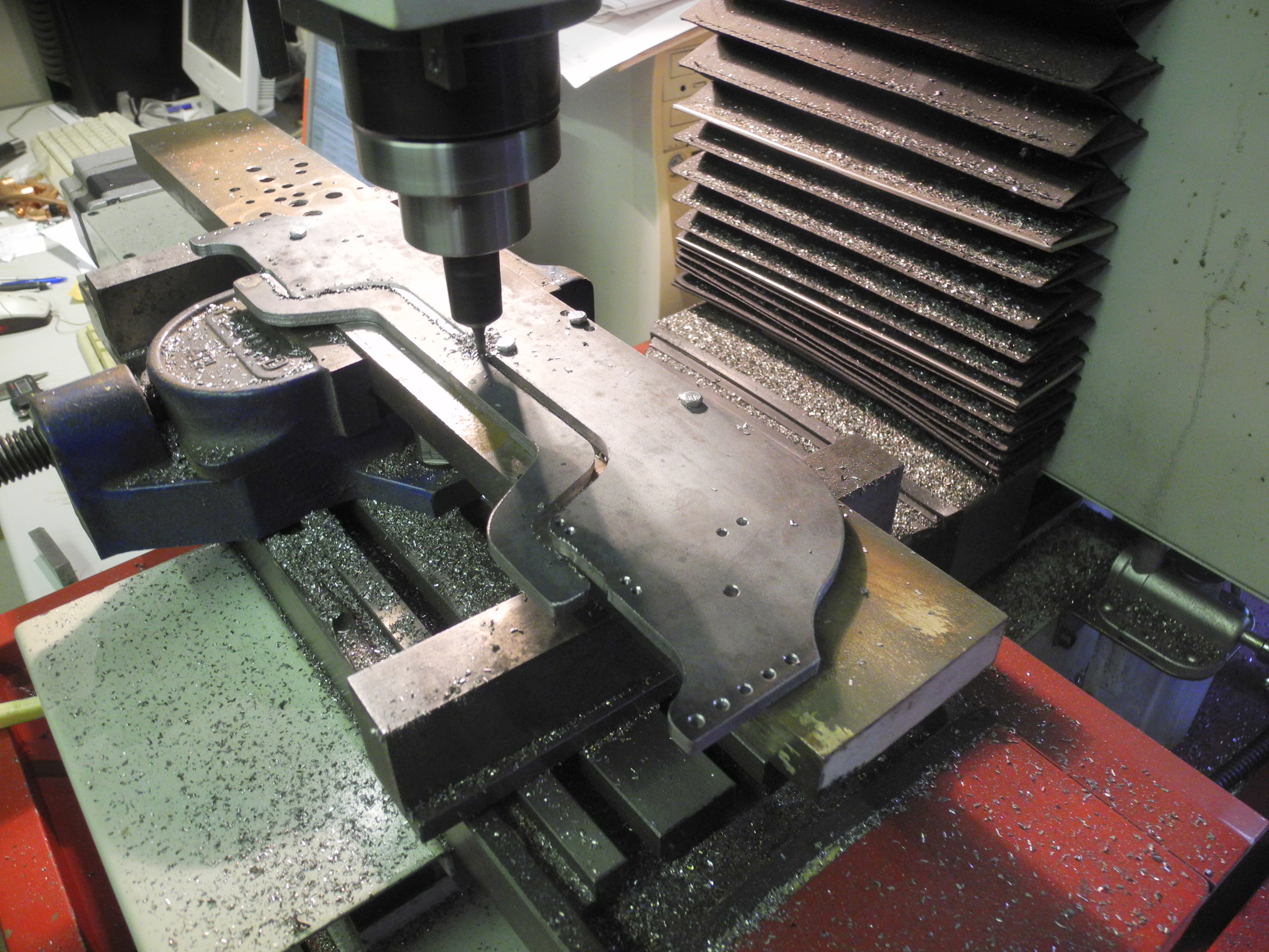
Photograph 3 - Frame cutting
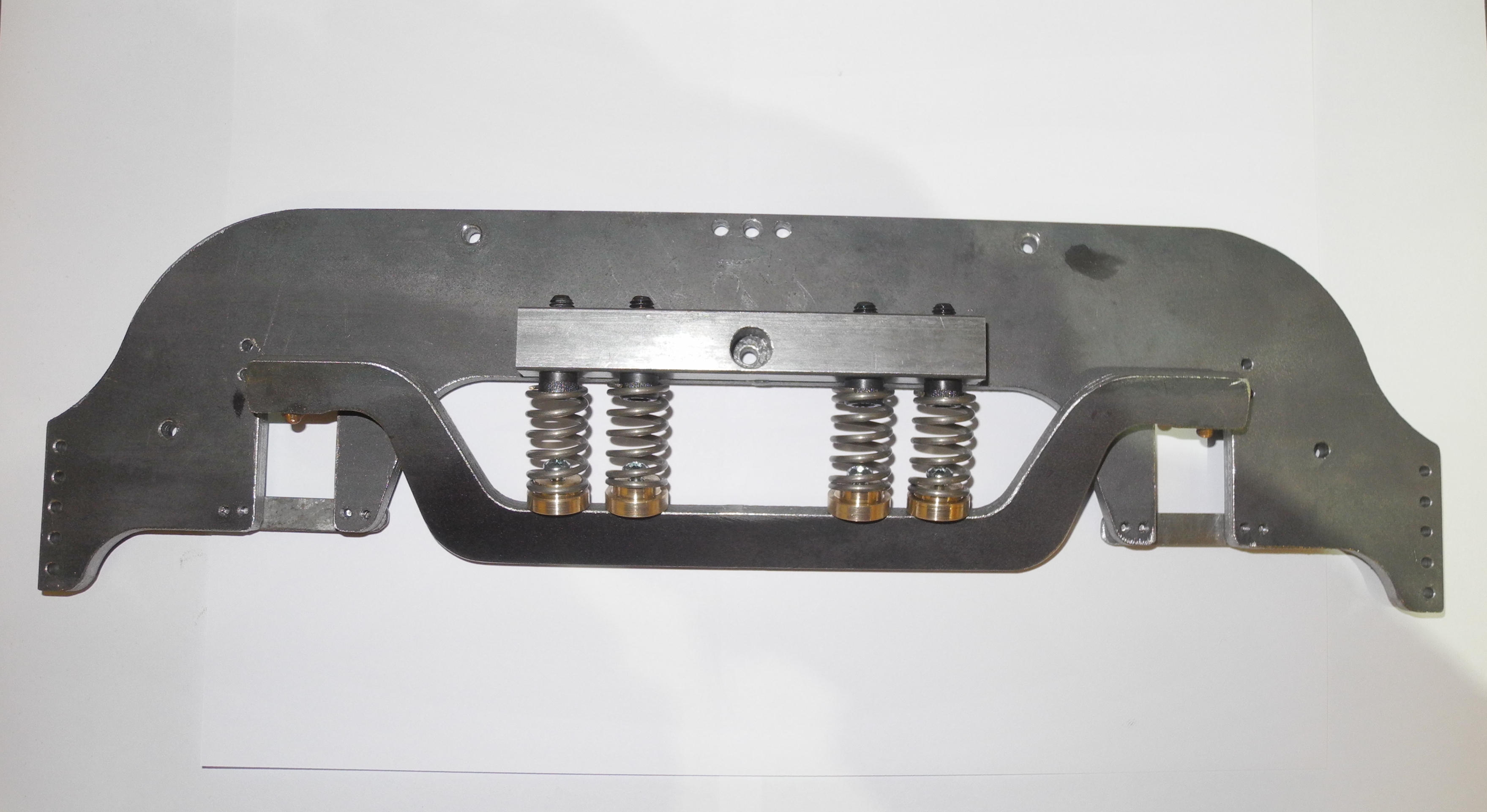
A length of four inch by quarter steel had been taking up space for a number of years just waiting for a good use, the time had come. With the material chosen, the frame design was progressed. The curves were drawn to be pleasing to the eye while leaving plenty of metal above and around the horn openings, and it seemed there was the opportunity to cut a useful suspension component out of the same pieces of plate. Figure 3 shows the frame profile with the suspension girder shown in red. Flipped upside down, this could bear on top of the axle boxes and hang down below the frame between axles, as inspired by D7017.
The two bogies may be identical, there being no obvious reason why they should not be. Using a similar logic, the bogies could be symmetrical front to back. Of course this hardly matters if cutting the frames by hand or if obtaining laser-cut items, but this workshop is equipped with a small CNC milling machine, too small to cut the frames in one go, but big enough to cut half a frame at a time. A good method would be to cut one end, flip the frame over and cut the other end (Photograph 3).
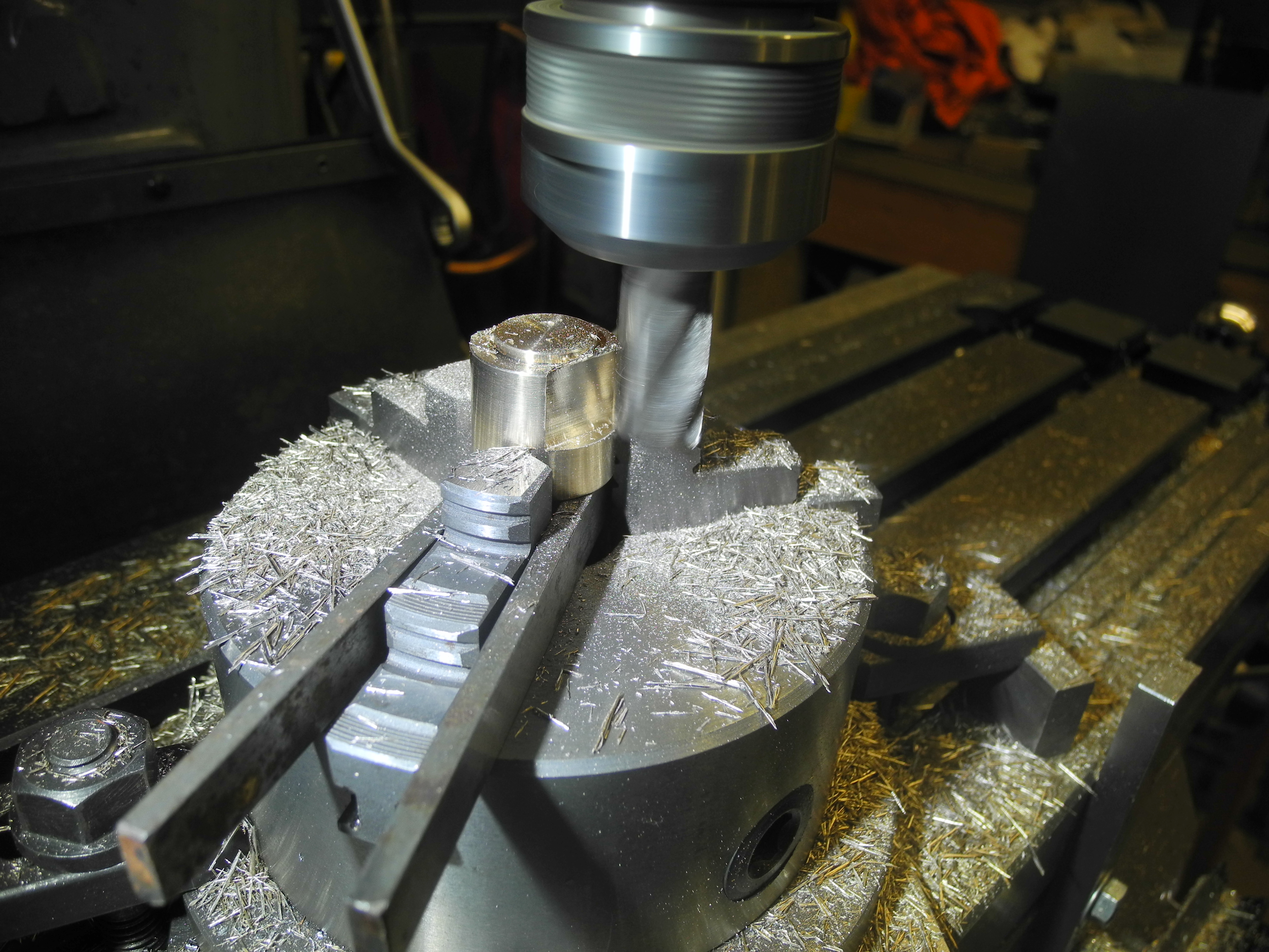
Photograph 4 - Milling axle box flats
To axle box design. Most locomotive designs seem to use square or rectangular axle boxes. Part of making these invariably involves milling two faces to fit the horn opening. A quicker method might be to machine these from round stock, blind bored to take a roller bearing, and with a pair of flats milled on the outside to be a snug fit in the frame horn openings. Machined from brass or bronze, the outer ends would almost be the right colour.
Motors
With an idea of the space available, attention turned to selecting suitable motors. At this stage it was not too late to change the bogie wheelbase if necessary to fit everything in. Having had a look at various other electric locos that turn up at the club track from time to time, they all seem to use DC motors with commutators and carbon brushes. These motors fall into two basic types; the more recent designs using permanent magnet DC motors. Some of the older designs use motors with electro-magnets instead of permanent magnets encircling the rotor or armature, these are known as 'Universal' motors because they run using an AC or a DC supply. The universal motor dates back over a century and found early application in trams and electric railways. Being relatively cheap to manufacture they are still produced in volume today for use in domestic appliances such as vacuum cleaners, food blenders and washing machines. However they are noisy and inefficient, and any motor with brushes is potentially unreliable as the brushes wear out, or burn out. The low-maintenance design requirement implies designing-in reliability, which would suggest avoiding using motors with brushes, and so for this new design it was decided to use more modern “brushless” motors that have the advantages of being more reliable, more efficient, and smaller for their power.
Unlike older motor types, the brushless motor can not be run without an electronic power driver and controller. Brushless motors may be supplied with or without Hall effect sensors fitted. These sensors provide rotor angle feedback to the electronic controller. Without getting into too much detail, motors without sensors tend to be good for fixed-speed applications, but for the kind of speed control required for locomotive use, the added expense and complication of Hall effect sensors is justified.
Searching the internet for brushless motors quickly revealed there are essentially two market areas, industrial, and radio controlled models and toys. Proper, complete and believable specifications for motors from the latter area were elusive or non existent, and of the many hundred types looked at on a number of web sites very few had sensors fitted. Searching the industrial suppliers found many fewer motors but at least they came with proper and believable specifications and often a choice of sensor configurations.
Choosing a Motor
A number of locomotive kits use one motor for each driven axle. This scheme was chosen for our design as the mechanics to drive multiple axles from one motor can get quite complex and messy. Reliability is a design objective, simplicity should help. Other locomotives seen use multiple motors rated at 100 to 150 Watt each. An often seen configuration uses motors of quite a large diameter but just short enough to fit between the wheel backs. This makes for a neat direct drive from a pinion on the motor shaft engaging directly with a larger gear fitted to a wheel-back. The search for 'brushless' motors found that they too come in a variety of sizes and shapes, but because of their better efficiency and simpler construction, brushless motors are a lot smaller than older motors of a similar rating. Looking for 'off the shelf' motors for immediate delivery, I settled upon part number 5366030 from RS Components. Continuously rated to deliver a torque of 0.25Nm (Newton metre) at a speed of 4000 RPM, this equates to a mechanical output power just over 100 Watts, with short-term overload ratings at twice and three times this. Although just too long to fit between wheel backs, the smaller diameter meant there was plenty of room to fit two motors between axles of each bogie. The length of the motor meant direct pinion drive was not possible, however a solution using toothed belts and pulleys looked simple enough.
Using belt drive or direct pinion drive, it is important to keep the distance and angle between axle and motor shaft constant while allowing for suspension. This constrained thinking about methods of mounting the motors and suggested a mounting plate hung from bearings on the axle between the wheels. A simple restraint at the other end of the mounting plate is then all that's required to keep the motors at an approximately constant height above the rail, keeping the motor parallel to, and at a fixed distance from, the axle.
Looking at a web page of loco dimensions, a very common bogie wheelbase is 8 foot 6 inches, covering eleven classes of diesel loco including the HST. This scales to metric 230mm, bogie wheelbase decided and fixed, giving plenty of room to fit a pair of brushless motors.
Calculations
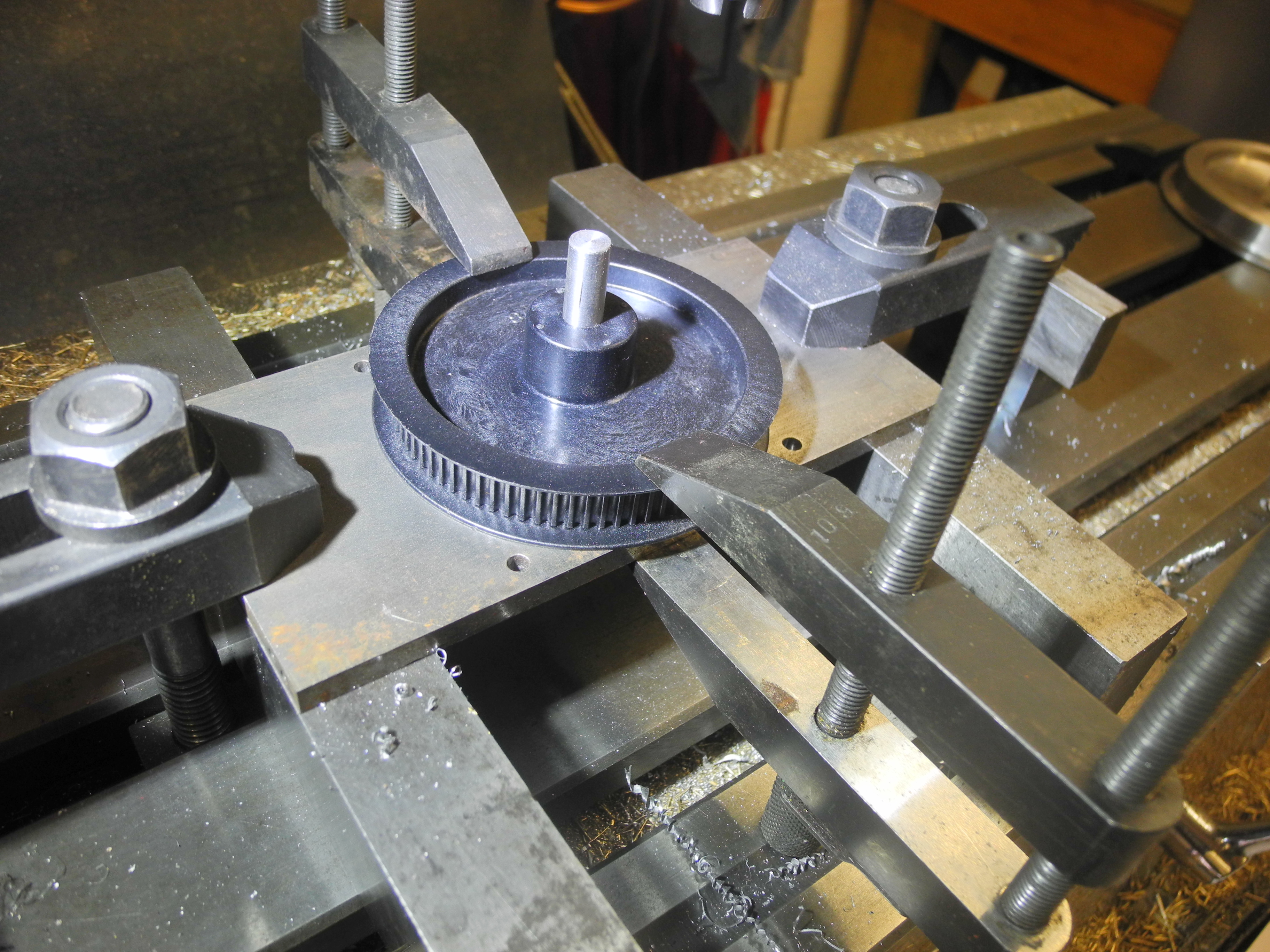
Photograph 5 - Large pulley to be drilled Photograph 6 - Drilling wheel for pulley
Some time was taken with the calculations, made much easier by use of a spreadsheet.
With an official speed limit of 6MPH on the club track, a maximum design speed of about 8MPH may be reasonable. With the wheel size chosen, this relates to an axle speed of about 660 RPM.
Looking at the available belts and pulleys, a type HDT3 belt was chosen, 9 mm wide with a 3 mm tooth pitch. The largest readily available pulley has 80 teeth and measures about 76mm or three inches diameter. This looked about as big as could be comfortably fitted to the back of a wheel leaving sufficient clearance above the track. The pulley chosen for the motor shaft has 14 teeth, this is not the smallest available however belt life is seriously reduced when too few teeth are engaged at any time. Deciding to use an idler wheel to adjust belt tension helps with this. The resultant reduction ratio of 14:80 results in an axle speed of 700RPM for a motor speed of 4000RPM, loco speed about 3.8 metres per second, or 8.5MPH. However, the motor is rated at full load torque at this speed, we can expect the motor to run much faster with a lighter load, so top speeds of 12 or maybe 15MPH might be possible. This suggested a higher reduction ratio might be used with advantage, however this would necessitate the added complication of a two-stage reduction using an extra shaft with two extra pulleys per axle. Another approach would be to design a limit on upper speed into the electronic control system. At the low speed end, driving the motor into the rated overload region, we could load the motors to, say, twice rated torque for the time typically taken to get started and up to running speed. This will cause extra heating in the motors and power drives, although this can be safely dissipated during the times of lighter load and no load. With these motors and the chosen belts and pulleys, the drawbar pulling force calculates to about 110N (Newton) at rated torque, 220N at starting torque. This compares to a calculated pull from a Polly I of about 200N with a boiler pressure of 60PSI, although wheel-slip probably limits Polly to rather less pull than this. Using the club passenger trucks with their ball or roller bearings, friction losses at low speed are small. Allowing for 10% of power being lost to friction, our loco could be expected to accelerate a load of 1000kg (equivalent to approx ten adults) on level track to track speed of 6MPH in around 12 seconds. A similar load could also be pulled up a gradient of one in fifty without coming to a stand. This should be more than enough for anything asked on our club track.
Reassured by the maths, and with bogie wheelbase and other dimensions settled, metal was cut. Photograph 3 shows a frame and suspension girder being slowly chewed out on the KX3 CNC mill. Photograph 4 shows an axle box being completed, the final machining operation was to mill a flat on each side to fit the horn openings in the frames. The diameter of the outer end was reduced to give some resemblance to the full size counterpart, the inside was bored to take a press-fitted needle roller bearing. A dimple was drilled in the top of each axle box, this locates a pin fitted to the suspension girders, keeping them in the right position.
Photograph 7 - Boring motor plate bush Photograph 8 - Coming together
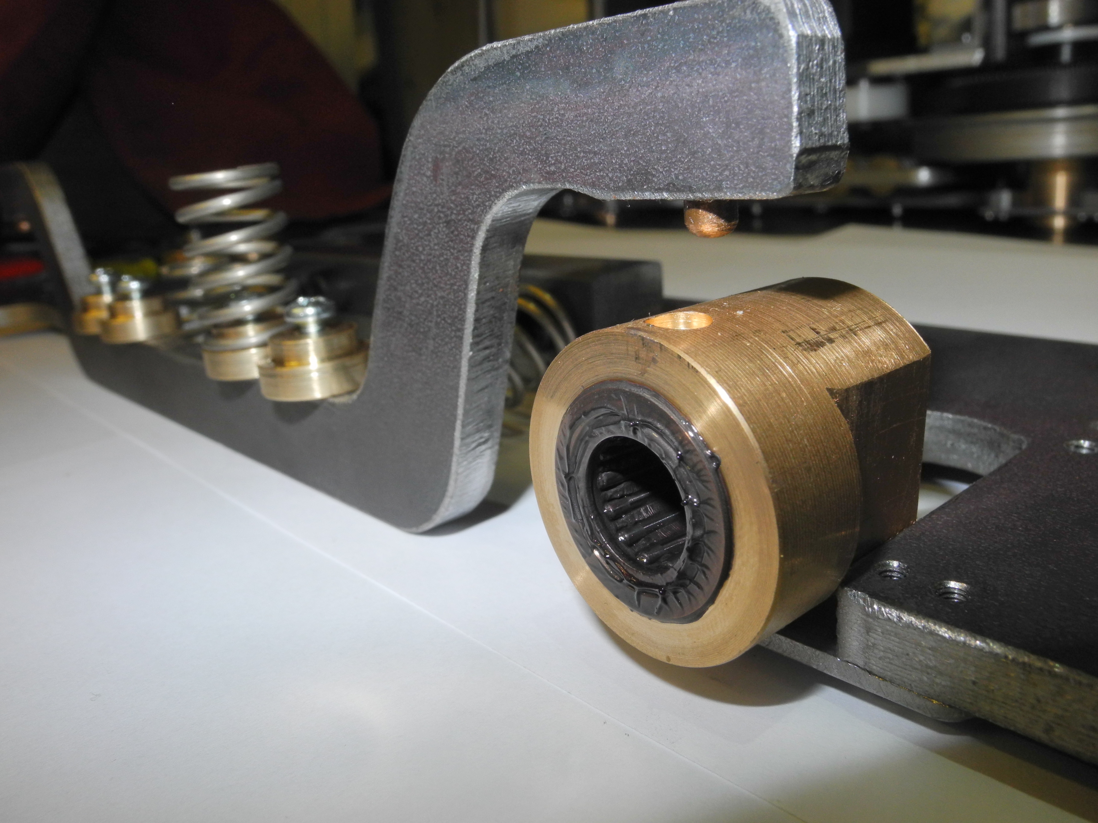
Mounting the 80 tooth pulley onto the wheel gave a slight surprise, the plastic pulley is hollow. For this reason it was decided to fix it in place using six screws instead of the two originally planned. Photograph 5 shows a pulley mounted on a drilling jig ready to be drilled, and photograph 6 shows a wheel being drilled using the same jig.
Another jig was cobbled up to bore out the motor mount bearing blocks. Doing it this way ensured all the bores were the same size and all at the same distance from the mounting face (photograph 7) The bronze bushes were bored to be an easy running fit on the axle.
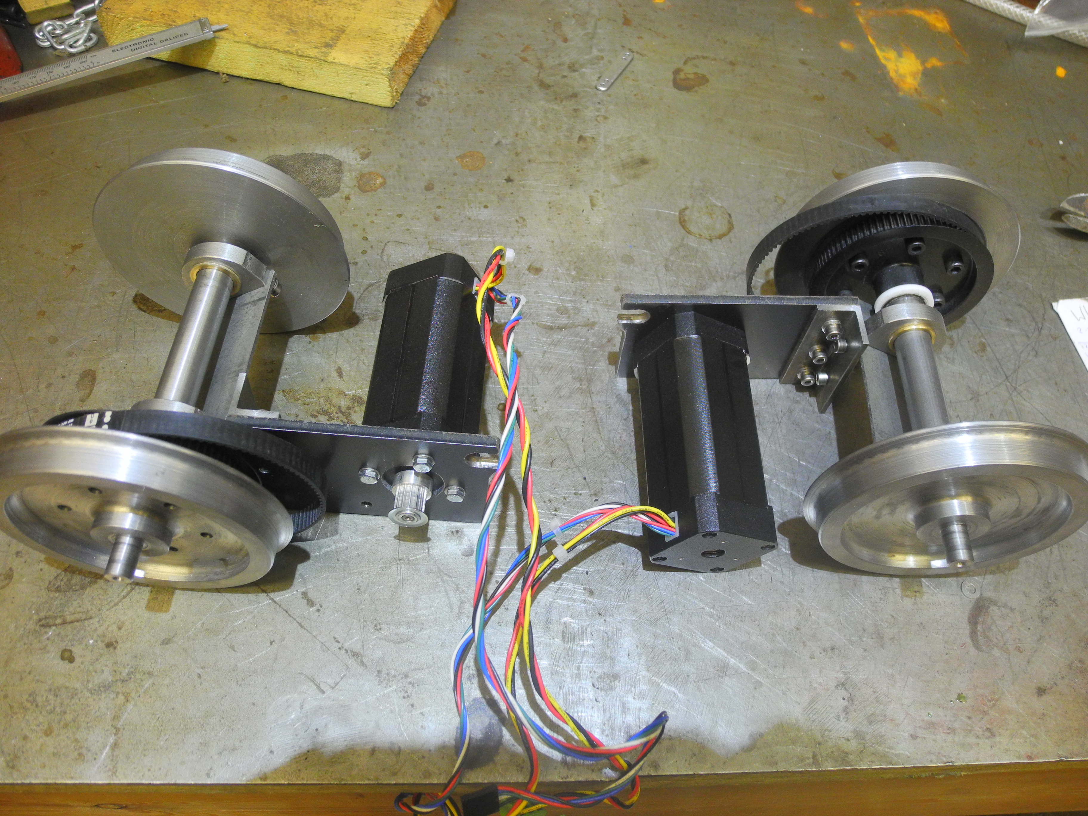
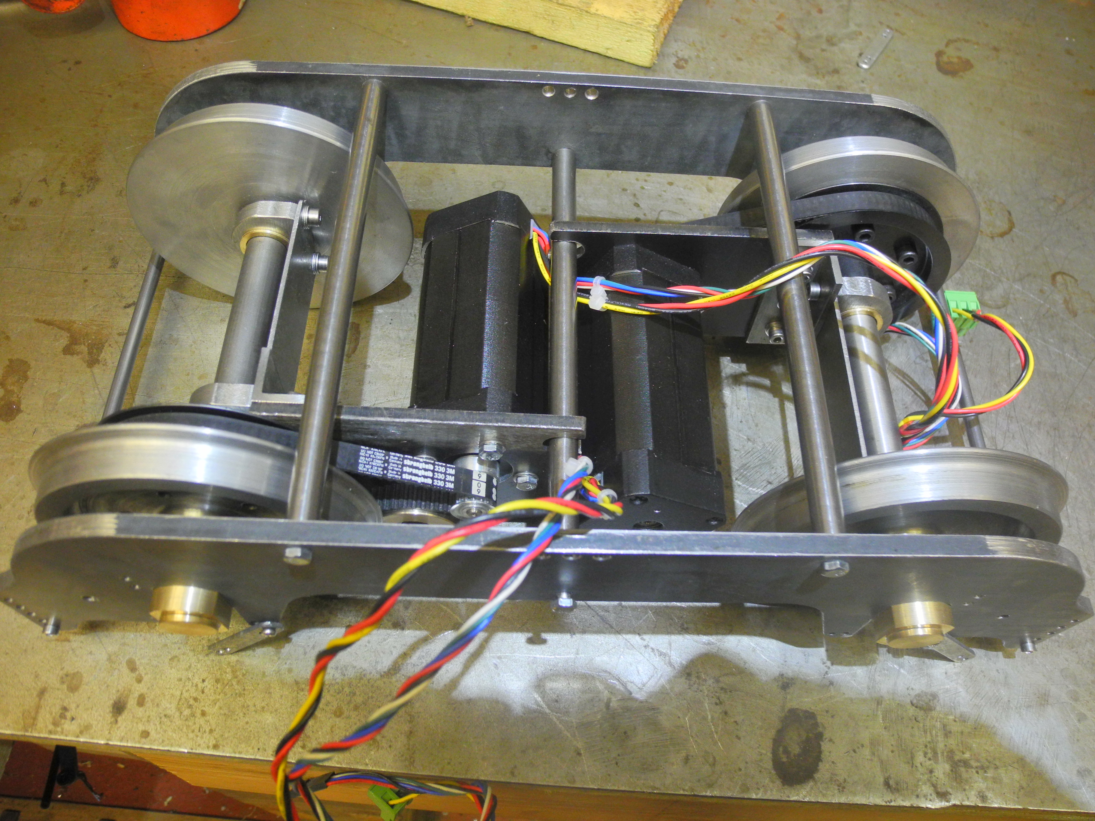
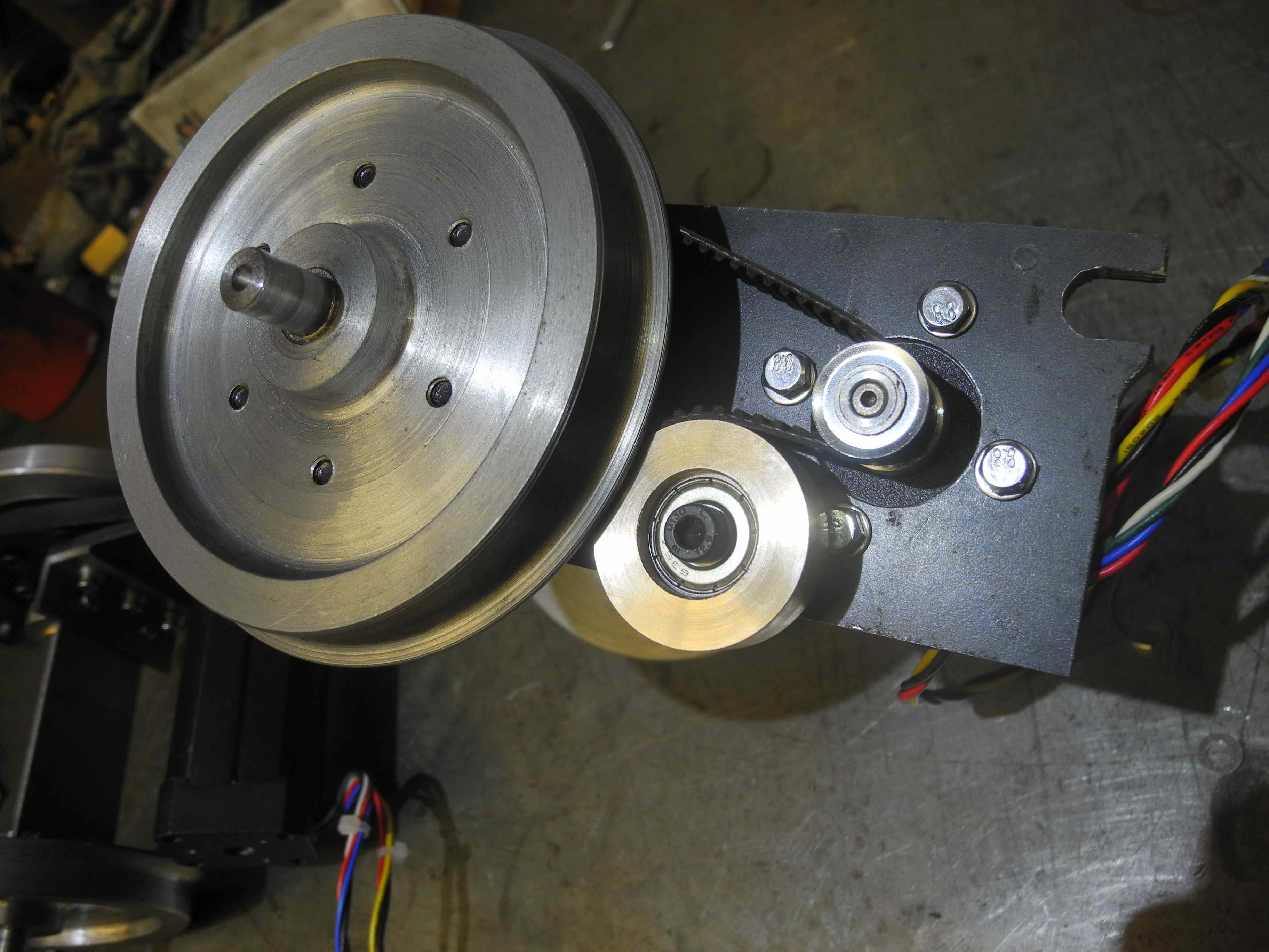
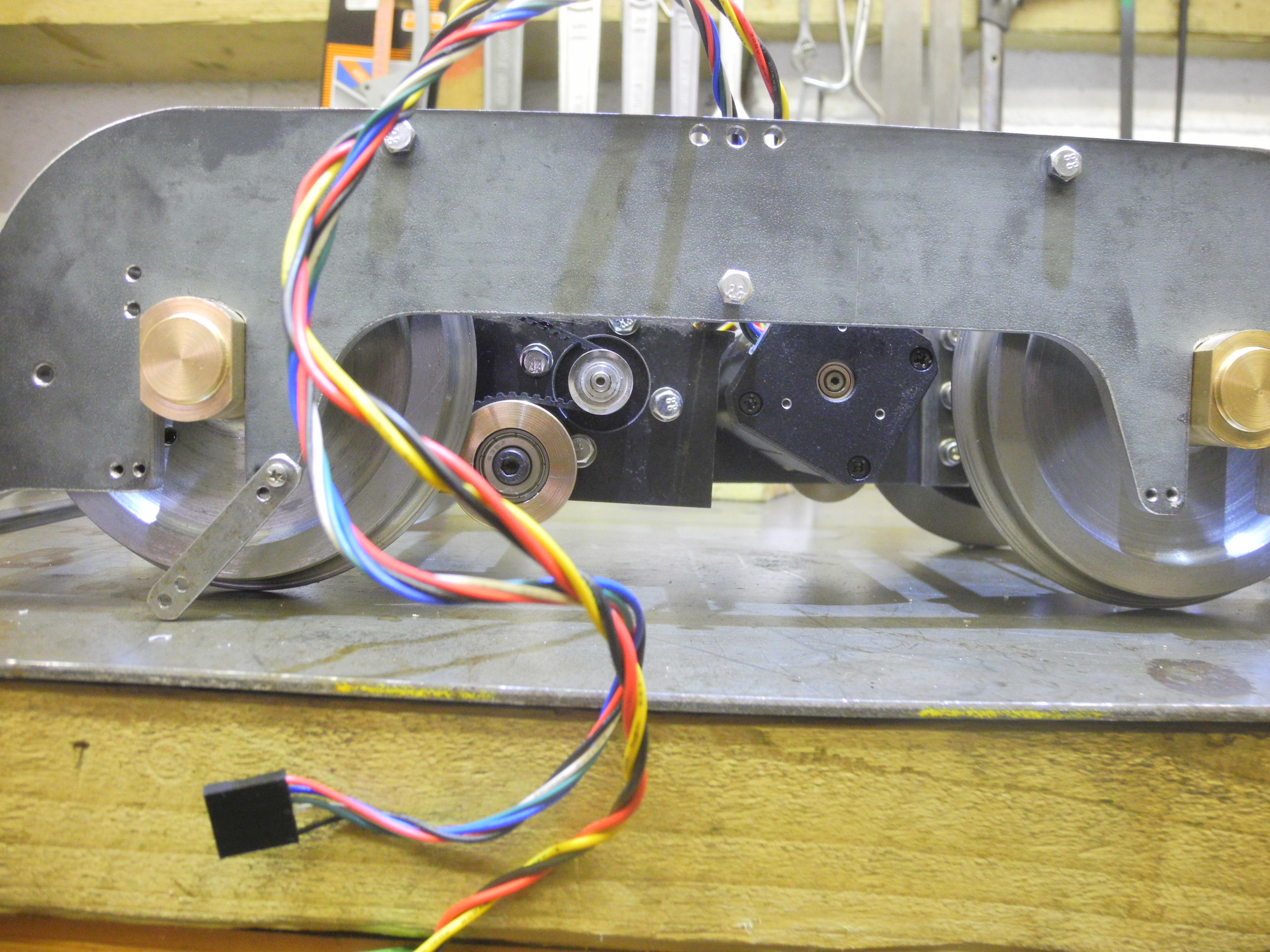
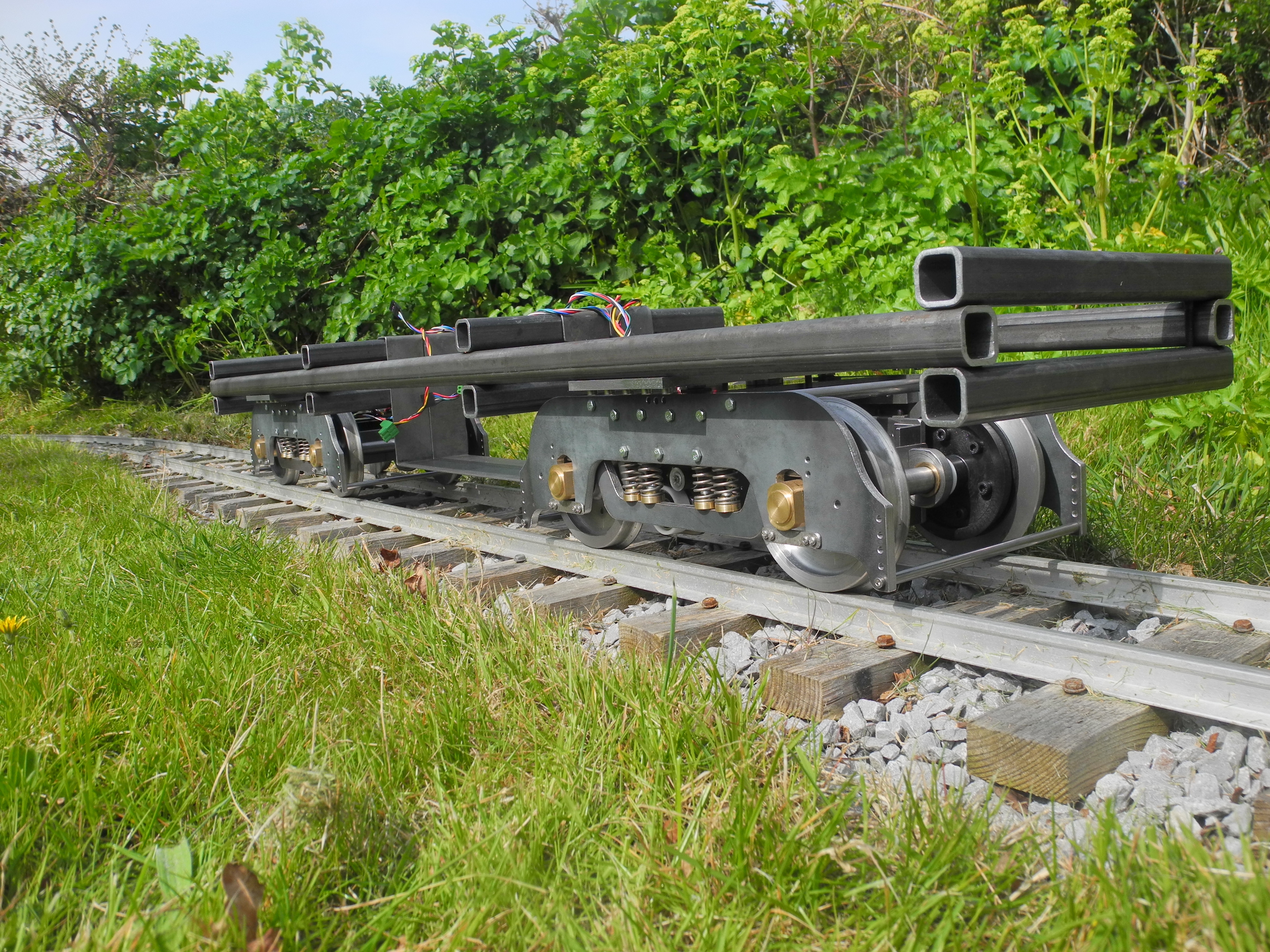
Photograph 9 - Bogie trial assembled Photograph 10 - Belt tensioning idler Photograph 11 - Bogie motor drive detail
Photograph 8 shows some of the main parts beginning to come together; in photograph 9 a bogie is together enough to start testing. Photograph 10 shows the belt tensioning idler which also serves to engage more belt teeth in the small pulley than would otherwise have been the case. Much fiddling with this tensioner has taken place and some doubt remains as to whether the belt is correctly tensioned. The idler is a ball race press fitted into a sleeve which bears against the outside of the belt. The only means of adjustment at present is by making another sleeve of a slightly different diameter.
By the time photograph 11 was taken only the suspension remained to be completed.
The Design of a Modern Electric
Locomotive in 5 inch Gauge
Published in Engineering In Miniature magazine Oct, Nov, Dec 2015
By Jon Freeman B. Eng. Hons
Part 2, November 2015, continued from October 2015
About Brushless DC Motors
Fig 4 - BLDC Star Windings
It won't be long before these so called “brushless DC motors” (BLDC) consign the older permanent magnet DC motor (PMDC) to the dustbin of history, but they are not directly interchangeable. One of the first things to learn about the brushless motor is that it is not a DC motor at all, rather it is a three-phase AC motor. It is the combination of brushless motor with its very necessary electronic power drive using fast electronic switches, and controller that can make it look and behave in a similar fashion to the old PMDC motors. Some small BLDC motors are already made with all the necessary electronics built in, making them 'look like' PMDC motors from an electrical point of view, and so very easy to use. Computer fans are one example.
Fig5 - Four Pole BLDC Motor
The two main components of any electric motor are electrical windings, and magnets in one form or another. BLDC motors exist in a number of design configurations, but what they all have in common is stationary electrical windings, and permanent magnets that rotate with the output shaft. In comparison the PMDC motor has fixed magnets surrounding the rotating, wound armature. BLDCs, having no brushes, are inherently more reliable, requiring little or no maintenance. They also have a better weight (or size) to power ratio and with fewer components used in manufacture. The size advantage arises because no space is needed for brushes, and in dissipating heat more effectively. In any motor under load, some of the electrical energy is converted to heat within the windings, this is known as 'copper loss', or I2R loss, which increases with increasing mechanical load. Some energy is also lost in the iron cores upon which the coils are wound - 'iron loss', which increases with speed. In the old PMDC motors, most of the copper loss and iron loss occurs on the wound armature - close to the centre of the motor. How fast this heat can escape limits the power for a given physical motor size. Some PMDCs include ventilation holes and a fan to move cooling air through the motor, risking allowing foreign matter in. With a BLDC, the majority of the copper loss and iron loss occurs in the fixed stator, nearer the outside, giving the heat a quicker and easier escape route. This means we can load a BLDC motor more heavily for a given size, without overheating. The motors chosen for this design are sealed giving no chance for anything getting in to gum up the works – another tick for reliable design.
Fig6 - Six Switches Three Half Bridges
The old PMDC motor has two connections. Apply a DC voltage and the motor rotates. Swap the polarity and the motor rotates in the opposite direction. High voltage gives high speed, low voltage - low speed. In locomotives of this scale it is normal to connect DC motors together (in series or parallel) and power them all together from one controller, typically a 'black box' bought in from one of the usual suppliers. To date nobody is selling a controller to drive these BLDC motors in this application.
The BLDC motor is not so simple to drive. Motors are supplied with three or more connections, the chosen motor has eight flying leads, three thick wires to carry the three-phase power and five thin wires associated with the three Hall effect sensors providing rotor angular position feedback to the control electronics (one wire for each of three Hall sensor outputs, plus two wires for a 5 volt supply to the Hall sensors).
The three phase power connections of a BLDC motor connect to three internal windings, connected together as shown in figure 4. By convention these three phases are labelled U, V and W. Figure 4 shows each winding in two parts which correspond to the six pole-pieces shown in figure 5. This is a simple arrangement to easily explain the workings and shows a 4 pole motor with 2 North and 2 South magnetic poles on the rotor. Many motors use more windings than this and rotors with more poles. This makes for better use of the space available for the windings and provides a smoother torque characteristic. The actual motors used are described as 8 pole, that is to say the rotor comprises 4 North and 4 South poles, surrounded by 12, instead of 6, wound stator poles. The 4 pole motor rotates half a revolution per cycle of applied AC voltage, the 8 pole turns only a quarter revolution per cycle.
With three power leads instead of the more familiar two, the controller will signal the power drive stages to sequentially switch any two of the three wires onto the battery supply. In this way, the magnetic field caused by the current flowing in the windings can be made to rotate. It is this rotating magnetic field which interacts with the magnetic rotor, causing it to rotate.
A point of interest, the rotor will turn through the same angle as the rotation of the magnetic field induced by currents flowing through the coil windings. As mechanical load on the motor shaft increases, so the rotor angle will lag behind by some small angle which increases with mechanical load applied. Once the load exceeds a certain point the rotor may slip too far behind to keep up and some fraction of a whole turn will be lost (half a turn for four pole, quarter turn for eight pole). This is the behaviour of a synchronous motor, quite similar also to the behaviour of a stepper motor, a close relative of the BLDC motor.
At any instant, any one of the motor terminals may be switched to connect with the positive supply, the negative supply, or left open circuit. This requires two switches per terminal, six switches in total, as shown in figure 6. The switches in the top row, S1, S3 and S5 are called 'high side' switches, those in the lower row the 'low side' switches. These switches are essentially the output stage of the power driver.
A switch is a binary operator – it is 'on', or it is 'off'. With six switches, there are 64 possible ways of setting them all (2 ways of setting one switch, 4 ways of setting two switches, 8 ways of setting three etc). Not many of these 64 ways make any sense for driving a BLDC motor, for normal running we require one of U, V or W to be connected to the positive supply, another of them connected to the negative supply, and the third switched off. This means there are only six of the 64 ways that are useful, although a seventh state 'all off' is also required and can be achieved in a number of ways. It should also be noted there are some very daft ways of setting the switches, any pair one below the other both 'on' causes a short circuit across the battery, a condition known as 'shoot-through', with the attendant risk of letting the smoke out. We need not worry too much however, as the electronic hardware can be designed, and the software written, to take care of all of this for us.
Fig7 - Motor Poles Table
To adopt a convention, let us say when current flows from the positive side of the supply into a U, V or W winding this produces magnetic North stator poles, and when current flows out of the U, V or W motor connection returning to the negative side of the supply, the stator produces South poles. When not connected and the current in a winding is zero it produces no magnetic flux and takes no part. From this the chart in figure 7 was prepared. State 0 is the 'Off' state where it is sufficient for any two, or all three, of U, V and W to be disconnected (put another way, for not more than one of switches S1 to S6 being closed). To rotate the magnetic field in the motor of figure 5 clockwise, the electronics will operate the switches through the sequence of states 1 to 6 in figure 7, working from 1 to 6 and then repeating. To rotate in the opposite direction the sequence will be 6, 5, … down to 1 and repeating. As drawn in figure 5, the motor is either unpowered (when the rotor may be in any position) or it is in State 5 where the pair of 'U' poles are 'S', the 'V' poles play no part and the 'W' poles are 'N' – remembering from school science lessons that opposite poles attract, like poles repel.
Fig8 - Hall Sensor Diagram
For the electronics to smoothly start and drive the motor it needs to 'know' what angle the rotor is at, at all times, and to energise the coils to rotate the shaft in the desired direction. This is where the Hall effect sensors come into play. The sensors act as low-power switches, each is 'on' for half a turn and 'off' for the other half, these signals are read by the controller as logic states '1' or '0'. The sensors are positioned at fixed angles from each other within the motor such that the three sensors provide an indication of which of six angle segments the rotor occupies. In the 4 pole design illustrated the sensors effectively divide each half revolution into six segments of 30 degrees as shown in figure 8 (the 8 pole motors have segment sizes half this, repeating four times per whole revolution). The three digit binary numbers shown in figure 8 represent a code relating to rotor angle which is read by the controller.
Fig9 - PWM Diagram
Having followed this far, there is a breathtaking simplicity in how the electronics works to drive the motor. Knowing what angle the rotor is at, and knowing the direction of rotation, the electronics sets the power switches for the next angular position to be reached, pulling the rotor towards that position. That's it. Please take a moment to reflect on this.
Of course there remains the question of how long this movement takes – the speed of rotation. As with many other types of motor, this is determined by two over-riding factors, the mechanical load and the applied voltage. The controller will need to respond to changes in mechanical load and to adjust motor speed by adjusting the applied voltage. This is achieved by a method known as 'pulse width modulation', or PWM. With PWM, the full battery voltage is switched on and off rapidly. The proportion of 'on' time is varied to vary the average voltage applied. Fortunately motors will run smoothly if the voltage is chopped fast enough. For example if the battery voltage is 24v and the power is 'on' for one third of the time, this averages to 24 / 3 = 8 volts. Figure 9 shows a PWM adjusting to produce a rising voltage.
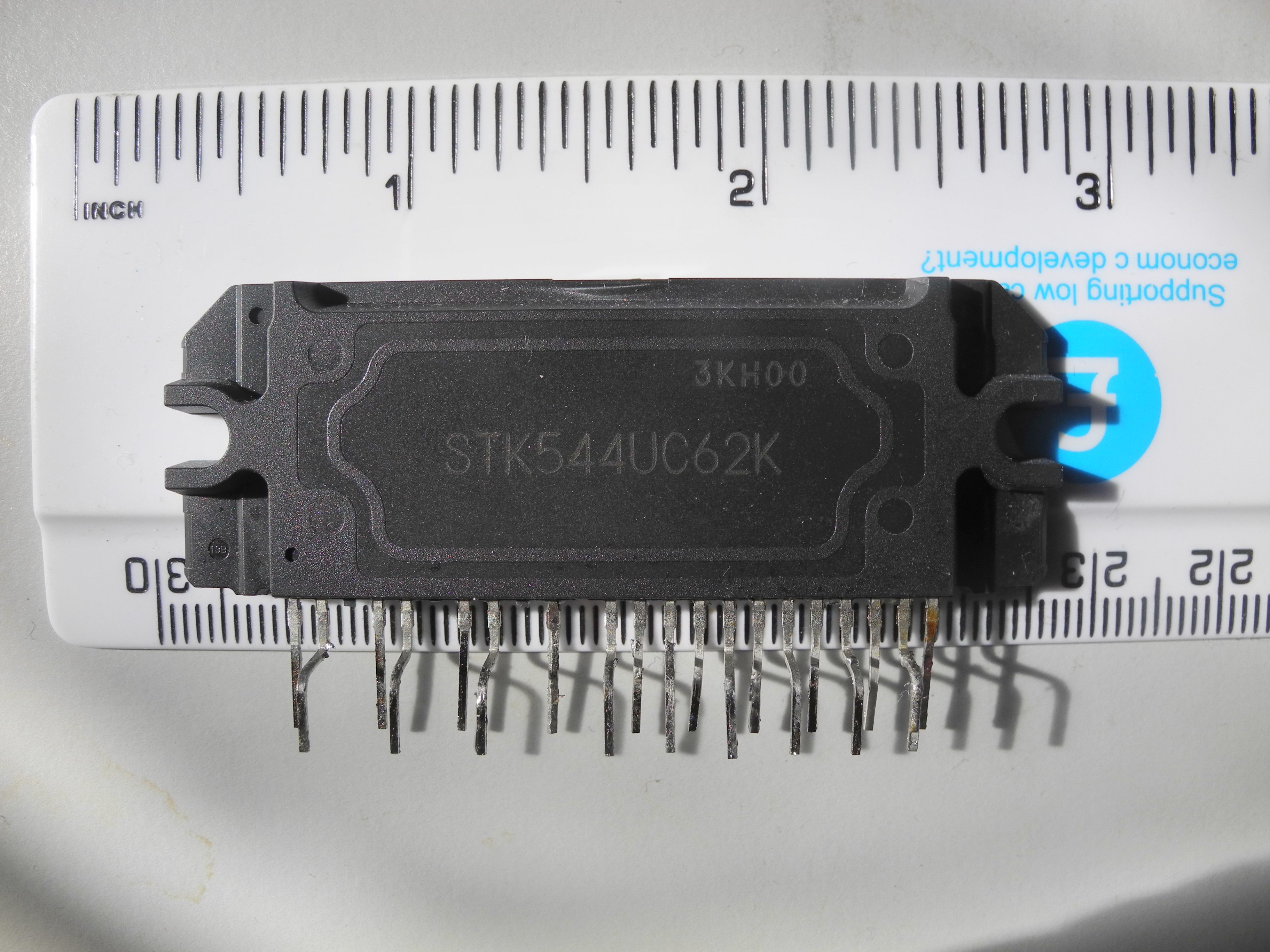
Photo 12 - Three phase motor drive module
Electronics Design By Catalogue
Electronic design has become so much easier in recent times. In the past design of a motor power drive would have required a working knowledge of analogue, digital and power electronics. The approach adopted here is to 'Design by Catalogue', not seeking to re-invent the wheel but to take advantage of readily available electronic modules. Knowing we need a set of six electronic switches to sequence power onto the motor power windings, industrial sources were searched to find a low-cost power-electronic module to suit. Unsurprisingly, we are not the first to search for a 'black box' to take care of all the nasty high voltage, high current switching of motor windings, and the On-Semiconductor STK544UC62K module (photograph 12) was selected from a long list of potential candidates, available from RS Components and Farnell, priced around £10. Designed specifically to drive three-phase motors at voltages up to 450 volts with current ratings of up to 20 amps, and with additional circuitry to protect against over current and over temperature, this takes all of the potential pain out of the design of a motor power drive. One of these is needed for each motor and each requires a number of other components around it, but all of this information is contained in the data sheet. There are six input pins which need to be driven by logic-level '1' or '0' signals to turn the individual switches on and off, and it will be the task of a central control computer to generate these signals in the time and sequence required. The computer will drive all four motor power drive modules.
The central controller is a Freescale KL25Z credit-card sized computer. This was chosen because it is very inexpensive, easy to use and awesomely powerful. The power comes from the use of the 'ARM Cortex' processor, a 32 bit machine. This makes it much more powerful than the 8 bit PIC or Arduino devices. Whereas we might succeed in persuading a PIC chip or an Arduino to drive four brushless motor controllers it would have been a struggle, if not a total waste of time. The ARM Cortex, being much faster and more powerful, can do this job comfortably, and at a cost of under ten pounds, it's cheaper than the Arduino! To programme the KL25Z, the programme is written in the language 'C' or 'C++' using an online compiler and downloaded over a USB connection. Any computer with internet connection, a USB lead and a KL25Z, there's nothing else you need to get programming. Any Arduino user would quickly be up and running with the KL25Z using the online compiler and resources at www.mbed.org
Fig10 - KL25Z Pinout
Figure 10 shows all the KL25Z connection points available for use. Many of these are user-configurable as digital inputs, digital outputs, PWM outputs and a number of other uses. The 'Analog In' pins are useful for measuring voltages, currents, temperatures etc.
The KL25Z computer is not directly compatible with the STK544UC62 power driver. This is because the motor driver uses a 5 volt logic-level standard whereas the computer uses 3.3 volt. However, this can be used to our advantage. As some interface device is required between the two to match voltage levels, it may as well do something useful as well.
Fig11 - Simplified Schematic to drive Single Brushless Motor
Looking at the two rows of power switches, in each row we only ever want one switch 'on', or no switches 'on'. Using a '1 of 4 decoder' logic chip, a two bit (two wire) connection to the KL25Z can be used to select any one of three switches, or none. Two of these decoders come in one chip package, 74HCT139, at a cost of a few pence. The decoders also have an extra 'enable' input. This is useful as a PWM output from the KL25Z can connect to one of these completing the design of all the voltage control electronics ! Note also the number of switch control lines is reduced from six to four. This thinking is illustrated in figure 11, a simplified diagram of the KL25Z computer driving a power drive output stage with the decoders as an interface between them.
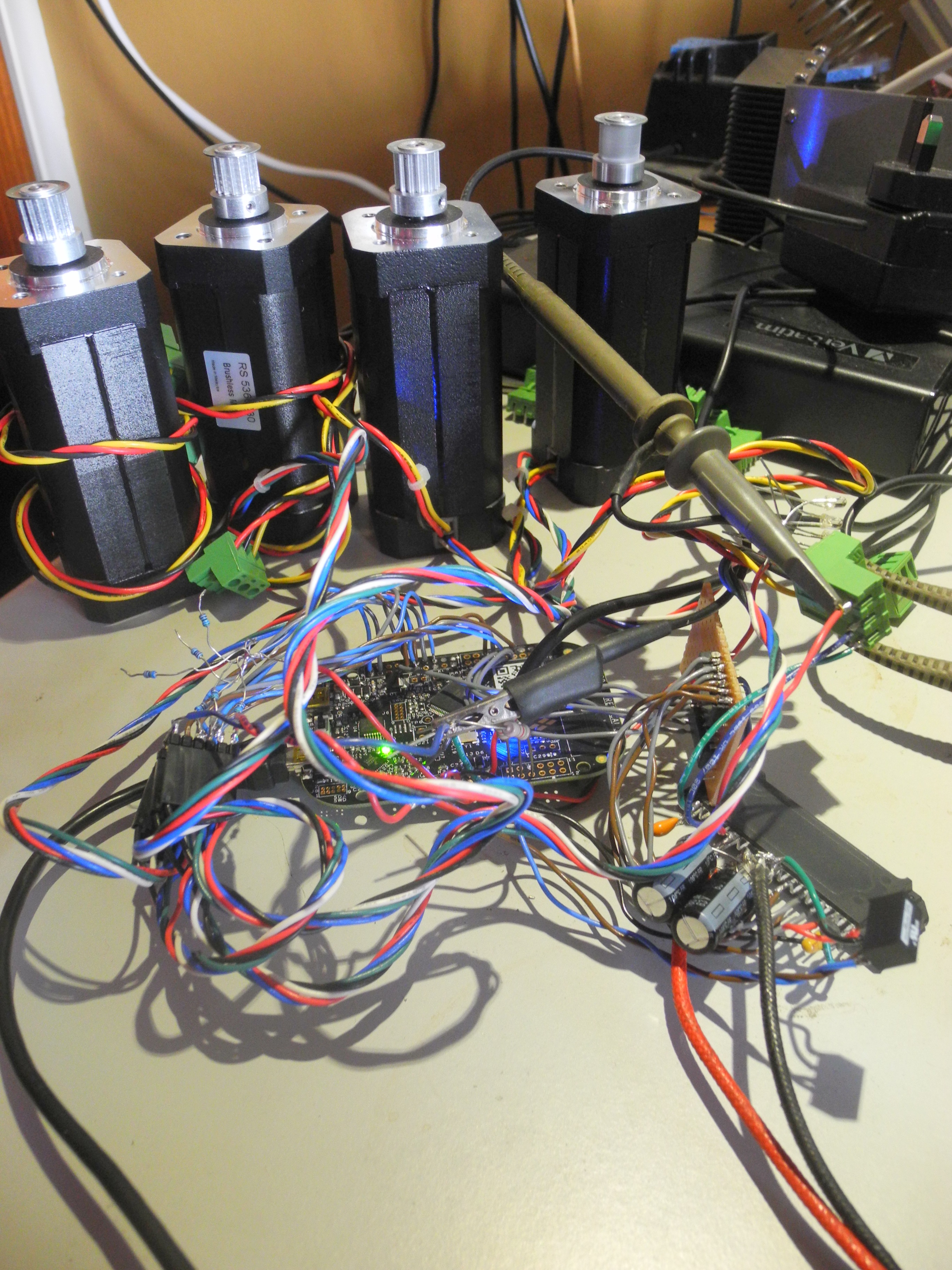
Photo13 - Rats nest
Photograph 13 shows the 'rats nest' prototype. At this stage all four motors had the Hall sensors connected to prove the KL25Z could read from all twelve simultaneously, but only one 74HCT139 had been lashed up on a piece of Veroboard and wired up to a single STK544UC62 motor drive module, complete with all the capacitors and other external components needed to make it work. The motor on the right in photograph 13 is running, it works!
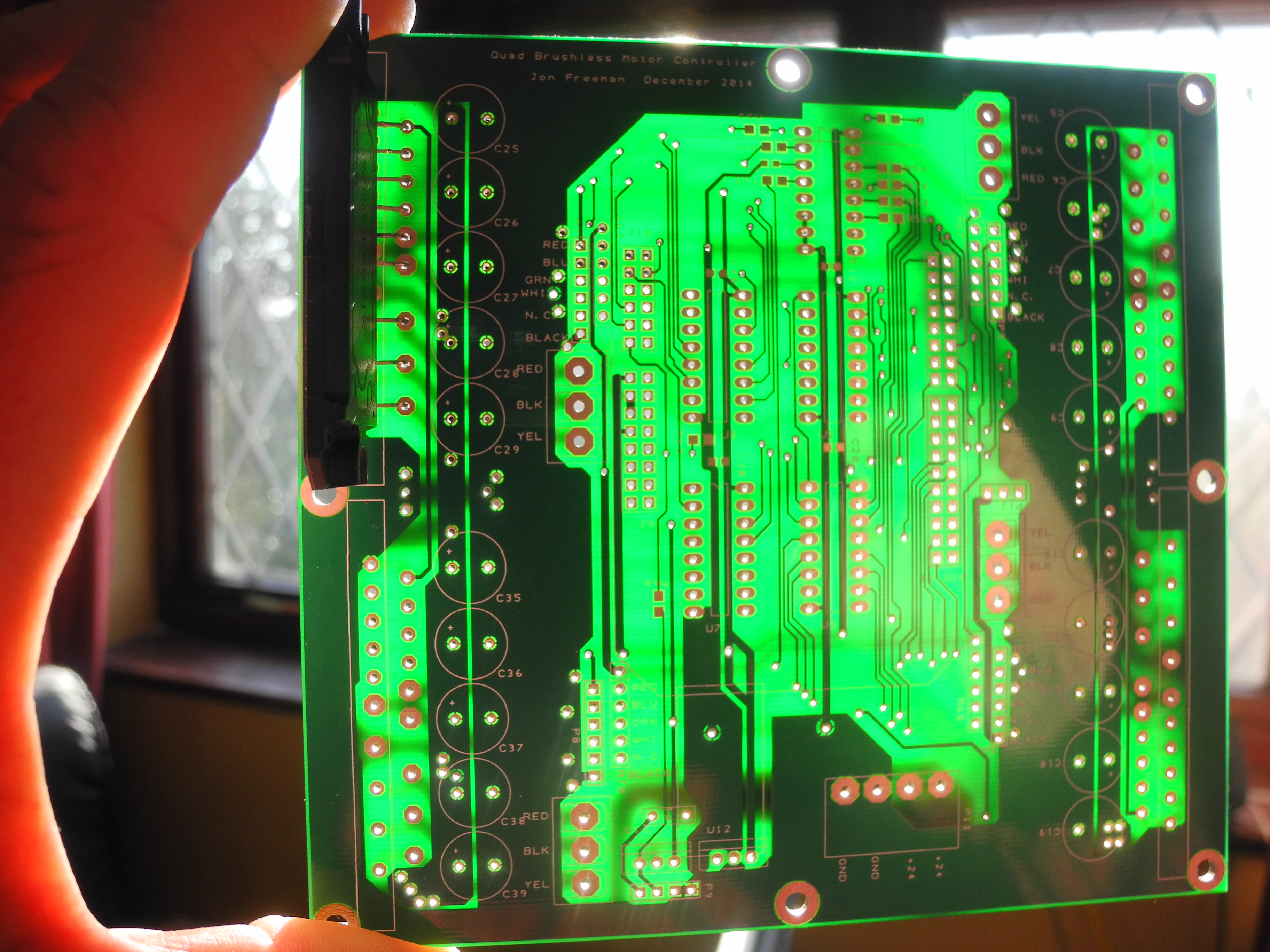
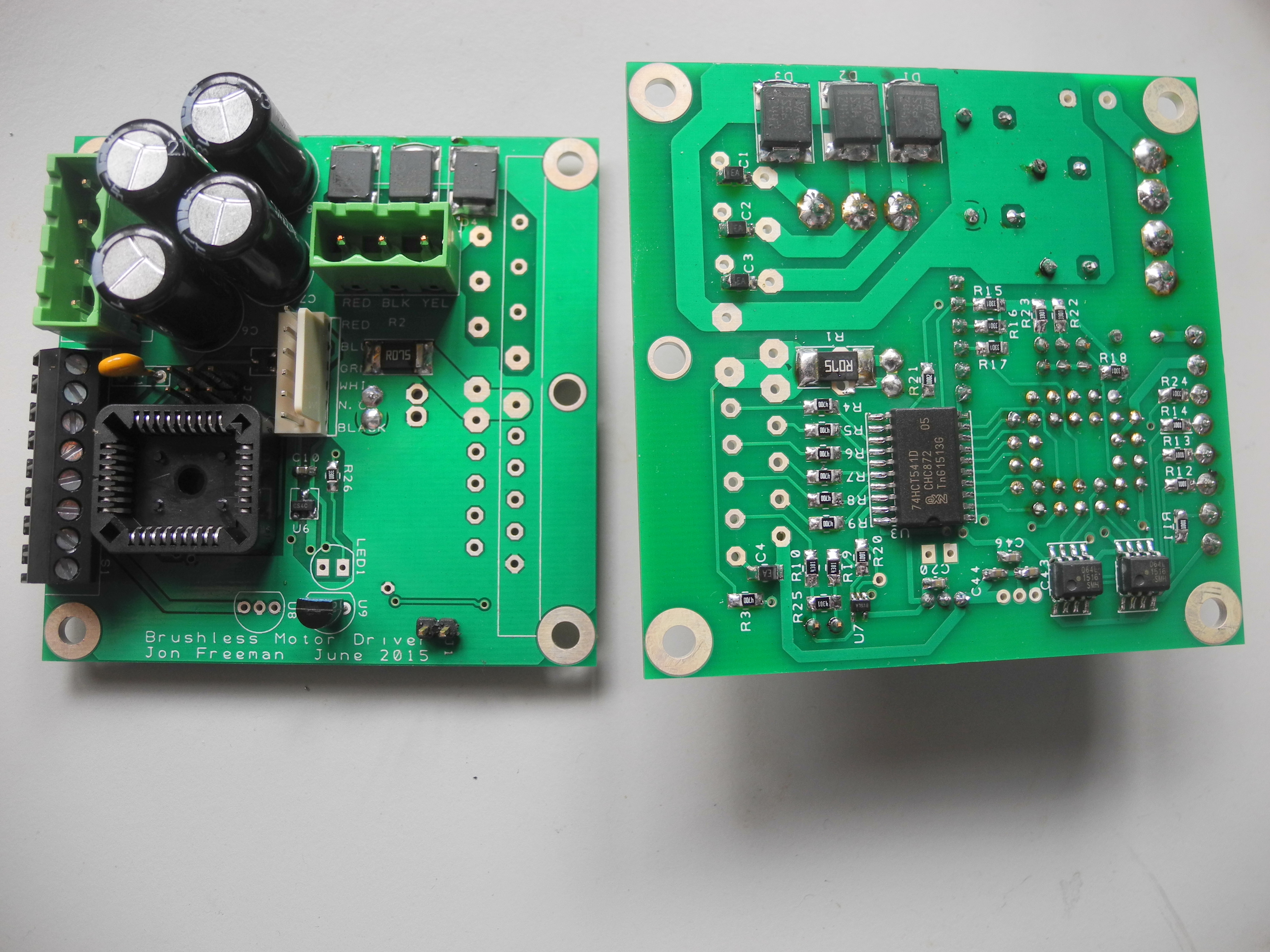
Photo14 - Bare PCB
Software
A brief word about the software, or computer programme, written to run on the KL25Z to make all of this work. It is all written in the 'C++' programming language in a form that's reasonably human-friendly, and runs to about 800 lines length in total, none of it is reproduced here. For most of the time, the computer is running around a programme loop repeatedly monitoring battery voltage, motor currents and motor drive temperatures. It is also monitoring switches and controls the train driver has access to, and takes care of adjusting the PWM to match the motor speeds accordingly. None of this is very time-critical, battery voltage and temperatures change slowly, train speed changes only slowly, and nobody would notice a half-second delay in response to the speed control. More interesting by far is the method used to control the motors. This uses a feature of computers known as 'interrupts'. The twelve Hall sensors are wired to twelve computer input connections, each configured to be readable to the programme as a '1' or a '0', and also to cause an interrupt to the computer whenever there is a change of state, either from a logic-level '1' to '0', or '0' to '1'. Thus the computer gets interrupted each time any motor rotor advances from one segment into another. In response, the computer suspends whatever it was doing and goes off to execute a piece of code known as the 'Interrupt Handler' (some writers call these Interrupt Service Routines or ISRs). In the interrupt handler, the computer notes which segment the interrupting motor has moved into and sets the power switches to pull the motor around to the next segment. This all happens very fast, and once complete, the computer quietly resumes whatever it was doing before. With an eight pole motor, the sequence of six segments is repeated four times per revolution, that means the computer gets 24 interruptions per revolution of each motor. Assume for a moment all four motors are running at 150% of rated speed, at 6000RPM, or 100 revs per second, this means the computer will get interrupted 9,600 times per second. This might sound like a lot, but the KL25Z spends only a tiny fraction of its time servicing these interruptions !
Having proved everything worked for one motor, this gave sufficient confidence that everything would work for all four. The next stage was to design a printed circuit board (PCB) to make a tidy job of things.
PCB Design
Photo15 - Assembled PCB
Not a job all model engineers would want to tackle, but like much else in electronics today, PCB design is easier than it used to be. The software used was 'Easy PC'. Using the schematic capture feature, the circuit diagrams are drawn, parts mapped to components and a PCB file is created. All the components are generated and can be dragged and dropped into the desired position and shuffled around on the PCB. Sorting out a baffling tangle of interconnections is made much easier using a double sided board with tracks on one side running predominately east-west, and tracks on the other running predominately north-south. Using 'plated through hole' (PTH) technology means you don't need to solder both sides of the board as all the holes are lined with tinned copper, making through-connection.
Once Easy PC had reported the design was complete and without error, the output files were emailed to a PCB manufacturer. A few days later a package arrived. A one-off would have cost around £130, or three for £150. I have two spares. It took a few hours to build and test one. Powered from a 28 volt supply, the board drives all four motors at no-load speeds up to nearly 7000 RPM. Using one PWM to set the voltage to all four motors means they all run at the same nominal speed. However, load differences will cause them to run at slightly different speeds. When running as a loco on the club track this would allow one axle to slip a little while the others kept their grip. The torque available from the slipping axle would drop as the speed rises so tending to automatically recover from a wheel-slip. Because the control computer is constantly monitoring motor speeds, it also detects a slip of any one or more axle and may respond by briefly breaking power to any motor for long enough to stop the slipping.
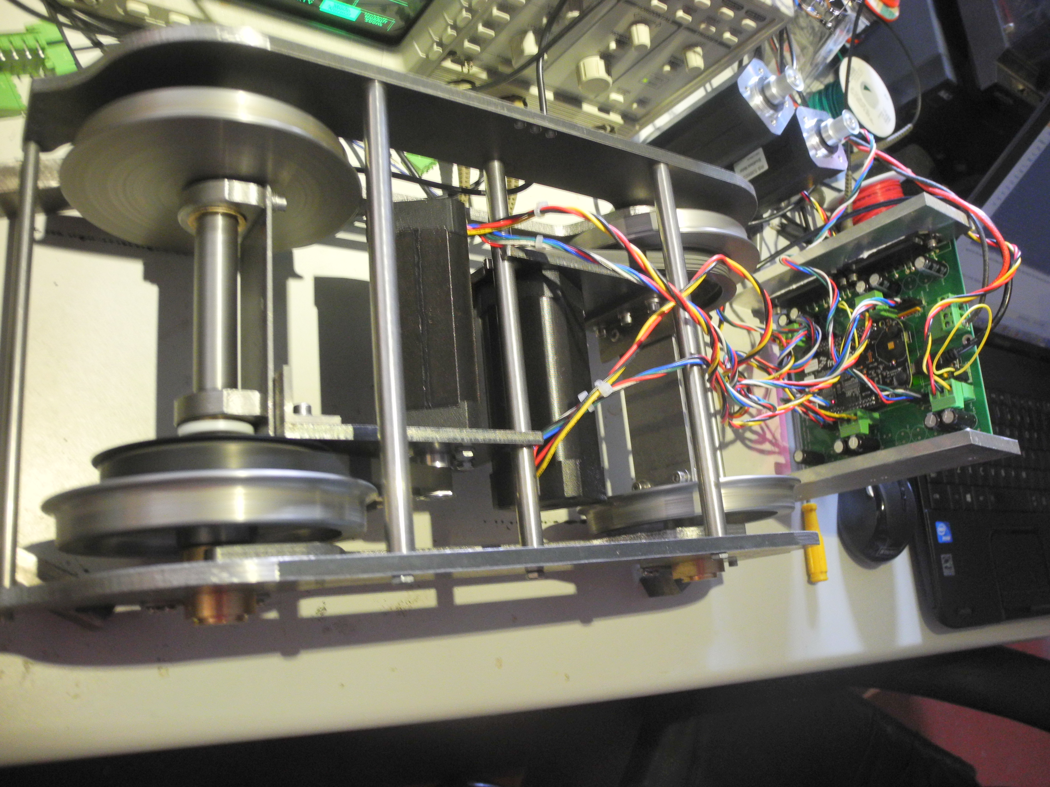
Photograph 14 shows a bare PCB and photograph 15 shows one built. Photograph 16 shows one part-built bogie jacked-up on the bench and being run at speed, driven by the circuit board. The other two motors are seen running, the second bogie was later brought up to match the first. Note the motor power drive modules are fixed to aluminium blocks screwed to the board. These are to conduct heat away from the motor drivers which will warm up under heavy load conditions.
Quite deliberately the surface of the electronics and software has been only lightly scratched, it is appreciated the electronic aspects will not appeal to all readers. For those interested in greater detail of the electronics or the software, it may be found at www.jons-workshop.com
Photo16 - A fully working bogie
To be continued …
The Design of a Modern Electric
Locomotive in 5 inch Gauge
Published in Engineering In Miniature magazine Oct, Nov, Dec 2015
By Jon Freeman B. Eng. Hons
Part 3, December 2015, continued from November 2015
Suspension
With the control electronics working and with the motors turning the wheels, the first test run was in sight. To complete the bogie assemblies, all that remained to sort out was the suspension. Completing some workable loco prototype required the yet to be designed chassis.
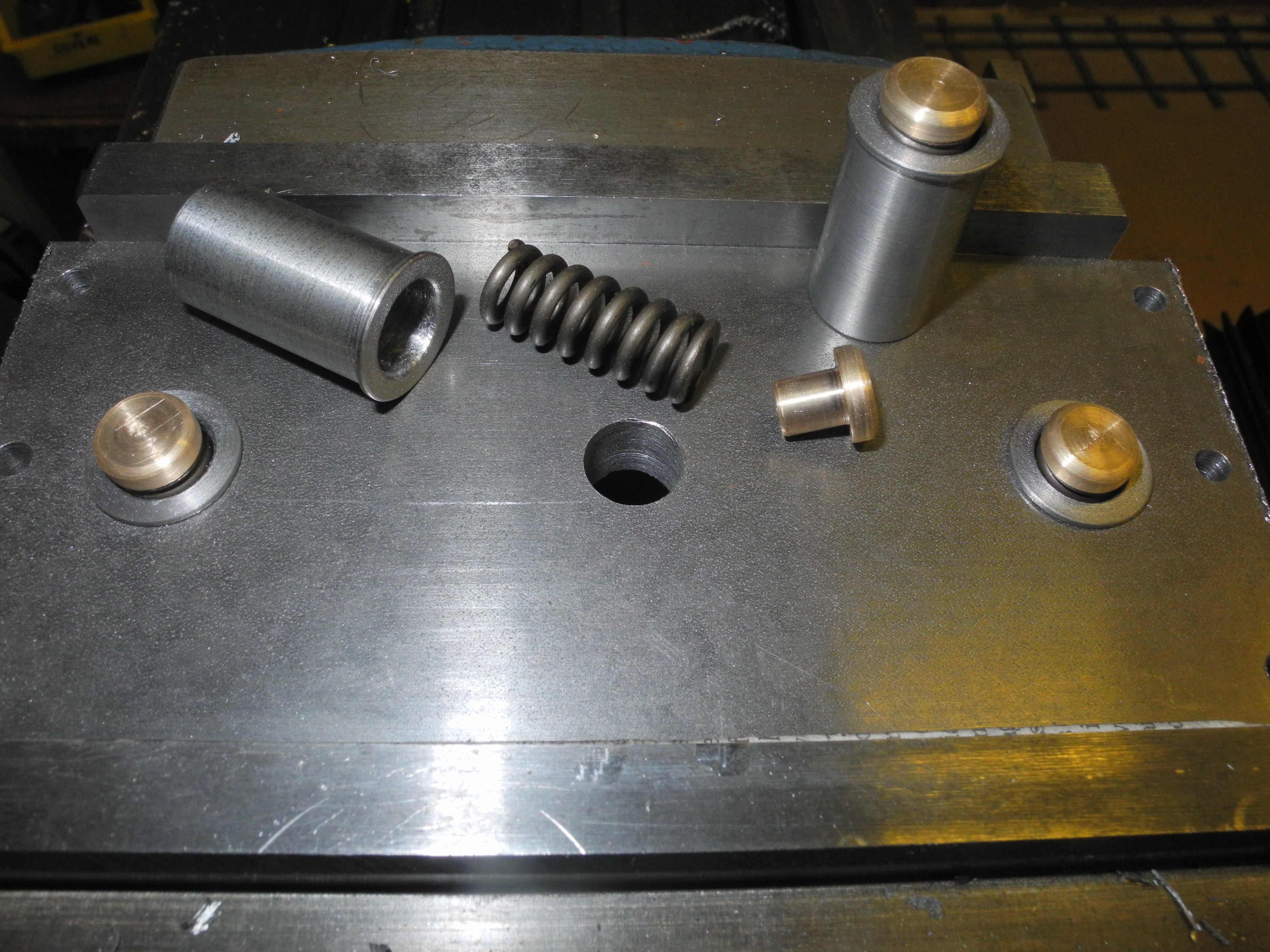
Photo 17 - Suspension parts
Looking back at the pictures of Hymek D7017, the suspension girders supported two coil springs, one near each wheel, with some kind of leaf spring arrangement in the centre. As the pictures were for inspiration only, the intention was never to copy a Hymek or anything else, I decided upon using four coil springs each side of the bogie supported by each suspension hanging girder, two springs close to each wheel. This, I reasoned, allowed greater flexibility in tweaking the springs for the best ride as half or all of the springs could be changed to adjust the ride height. As for the leaf spring, I wasn't too sure of the purpose of this, but I had thought ahead about the reality of any club track which would probably look a bit uneven if scaled up to full size. One place on our club track had become notorious, known to some as “dead man's curve”. If anyone was going to have trouble, that's the place it will be. That said, not many locos suffer any problem at all, but the Polly has bounced off the track a few times here, as have some other locomotives. I have an unprovable theory that the problem could be due to changes in camber, and with this in mind I decided to include some extra springing to allow the two bogies to tilt to accommodate a little opposing camber. This might have been what the leaf springs on the Hymek were about, and in this design the bogie mounts have a pair of additional springs between the bogie and frame mounting. These are not visible on the assembled model.
Working out a first 'best guess' at the springs and suspension was not too difficult. The bogies had been designed to allow a 'reasonable' vertical movement of the axleboxes. There doesn't seem to be any hard and fast rule about how much movement should be allowed, and the measurement chosen in this design was 'something close to true scale plus a bit' – about 7mm. It seemed reasonable that the springs should still just be under slight compression with the axleboxes at the lower limit of travel, this ensuring the spring can push the axlebox down fully. It seemed reasonable also that under static conditions on a perfectly level track, all axleboxes should be about half way between upper and lower limits of travel. With this decided, next was the task of guessing the approximate weight of the finished locomotive, a figure of 50kg being used. Then allowing for sixteen springs to share the weight equally, each spring would be compressed about half a suspension-travels-worth with this force applied. Some swift calculations to convert this to Newton per milli metre, the spread sheet came up with a figure of 8.7 Newton per mm. A suitable spring size was 25mm length and any diameter from about 12 to 18mm. Stock number 1048 from Entex Stock Springs with a rating of 7.7N/mm was selected for the first try (subsequently half the springs were changed to the 'next stiffness up').
Photograph 17 shows how the suspension was arranged. Lengths of rectangular steel were screwed to the inside of the frames with the bottom edges flush with the bogie frame edges. These had been drilled and tapped to take the four cap head screws shown, the cap heads being ideal to locate the tops of the springs. Some simple brass buttons were turned up and fixed to the suspension girder with a single screw each. These form the feet supporting the bottom of the springs. This design allows for some height adjustment by packing with washers.
Photo 18 - Top hat parts
Photograph 18 shows the bogie top mounting plate held in a machine vice. The centre hole is the bogie pivot point, also shown are some top-hat spring pockets with bronze slipper-heads which locate in the top of the springs shown. The idea is that these top-hat spring pockets fit as shown, one towards either side, with the bronze caps bearing up on the fixed half of the bogie mount attached to the loco chassis above. This provides a little scope to accommodate bogies cambering in opposite directions.
Photo 19 - Suspension and axlebox
Photograph 19 shows some detail of the axlebox with the bronze pin fitted to the ends of the suspension girder. The pin locates in a shallow dimple on top of the axlebox and keeps the whole suspension system lined up and in the right place.
Main Chassis
With the power bogies all complete and ready to roll, it was time to think about the main chassis, it went something like this.
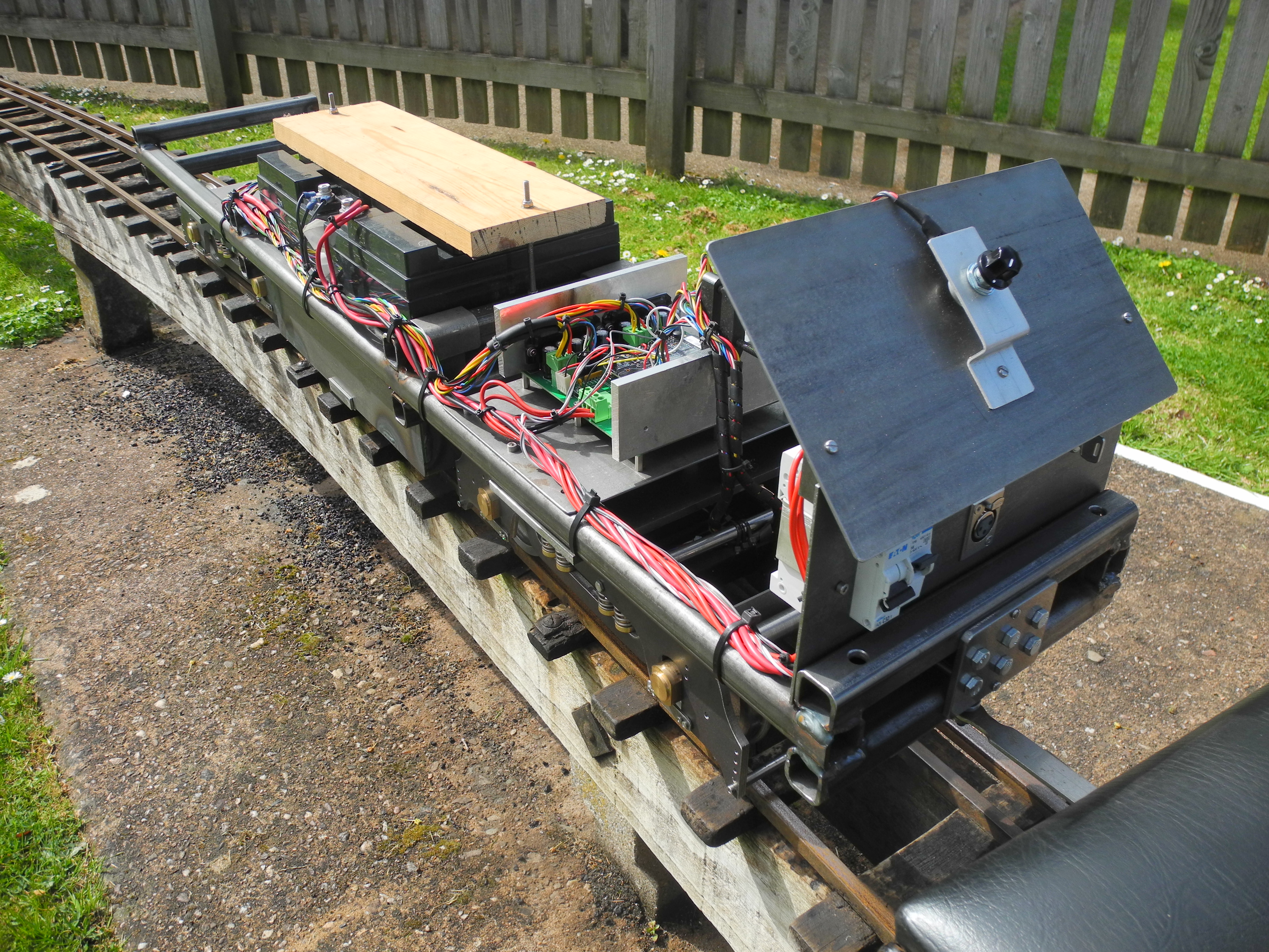
Photo 20 - The Chassis
Was the loco ever going to look like a classic British Railways Class something-or-other? Probably not, so what were the most important design considerations? Number one – it must fit in the car. There is no prospect of buying a van, trailer or new car. This determined a maximum length.
A very simple chassis frame was cobbled up using 25mm square steel tubing (photograph 20) and later welded up by fellow club member Dave Woods. A pair of battery hangers were bent up from sheet steel, these allow the batteries to hang quite low between the bogies, keeping the centre of gravity low. Two plates of 4 inch by quarter form the upper bogie mounts, these are screwed up under the main front to back chassis tubes.
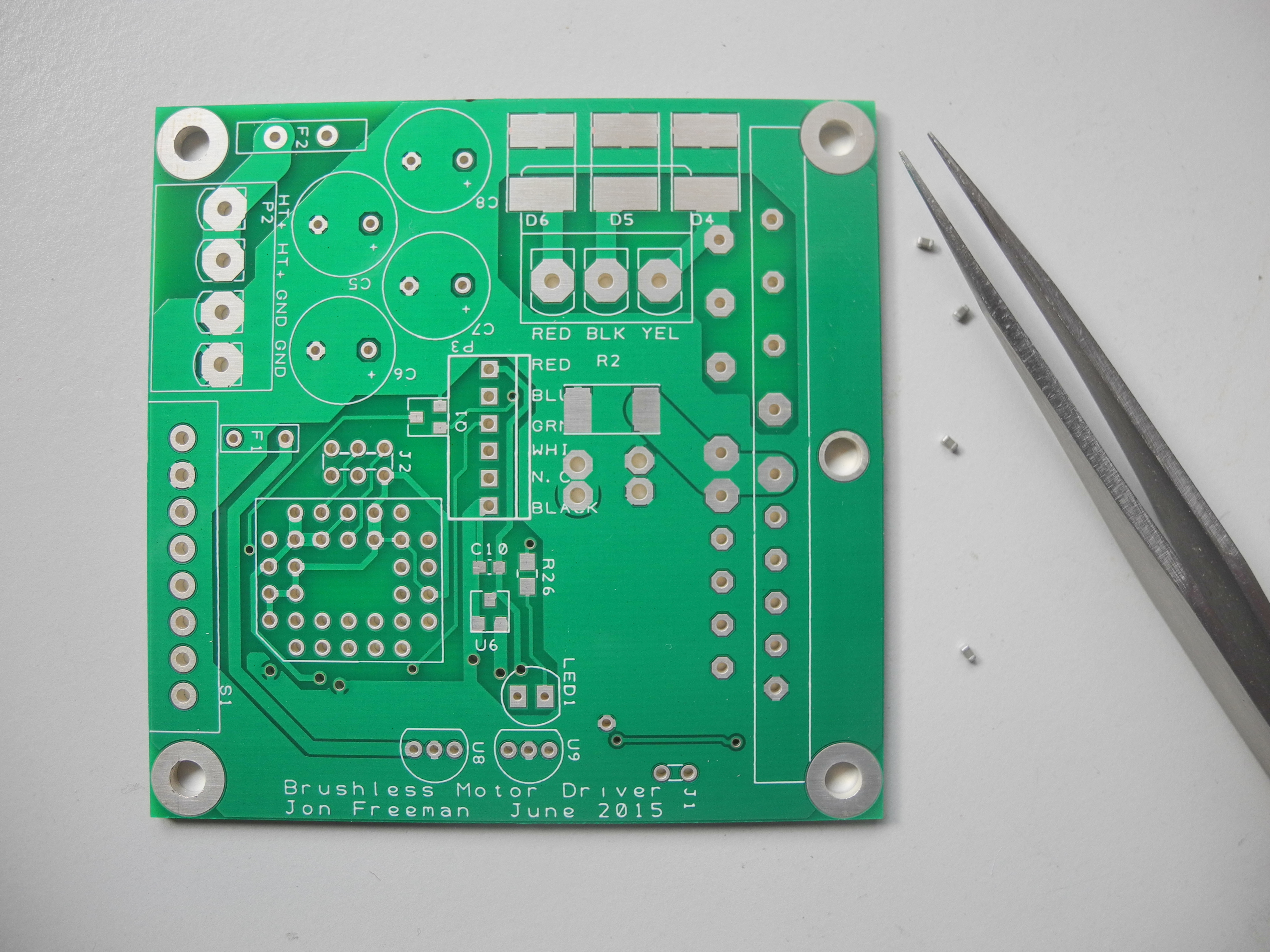
Photo 21 - Ready to go Photo 22 - Bare board tweezers and capacitors
Batteries.
It is a huge mistake to use car batteries. They are not designed for this job. Batteries designed for deep cyclic discharge are the ones to go for, the type used in mobility scooters being almost ideal. Another rule of thumb, go for the highest capacity batteries you can fit in the space available. Even when designed for deep discharge, batteries last longer the less they are discharged. If you only half discharge your batteries after a day at the track, the batteries will last years longer than half size batteries run flat every time. Another battery tip, when using multiple batteries it is a very good idea to treat them exactly the same, that way you are less likely to have one fail prematurely. In this design, two 12 volt batteries are wired permanently in series to give 24 volts. There is nothing in the loco that runs from 12 volts so there is nothing to load one battery more than the other. The batteries will stay in the loco, there being no good reason to remove them between uses. To charge them, a proper 24 volt mobility scooter charger was purchased. This plugs into a socket on the control panel so there is no mucking about with voltmeters or crocodile clips, just plug in after a day in the park and leave the charger to do its work. Modern chargers are intelligent enough to know how long to charge for and to switch into standby when their work is done. The batteries chosen were rated at 50 Amp hour, and if this were a scale model of a Class 43 or 26 or whatever, the two batteries could just fit lengthways between the two bogies. By making the locomotive chassis about a little fingers width wider than true scale, the batteries could be fitted with their longest dimension running from side to side so enabling a very useful saving of a couple of inches off the length.
Photo 23 - Boards under construction
Control Panel
The control panel design was thought out as being in two parts; the lower vertical section was planned to take the 'ignition' switch, battery charging socket and power breakers. The long term plan for the upper sloping section remains to include a liquid crystal display to show speed, battery voltage and current and anything else of interest, and for the panel to include some kind of joystick control for torque or speed demand as well as control over regenerative braking. However, to test the loco mechanics, a simple rotary speed control potentiometer was bodged into the electronics and temporarily attached as seen in Figs 34 and 35 The two circuit breakers; one switches power to the motor drivers, the other disconnects the battery charging socket. The key switch handles only very low currents and is a three-position switch. The centre position is 'off' and is the only position where the key is removable. The other two positions – forward, reverse. This switch feeds flea power to the controller electronics only. The heavy motor currents flow through the circuit breaker.
Trial Runs
We were ready for our inaugural run. With two other locos and drivers out on the club track, this left us only one passenger truck to haul, so we hooked up the coupling and took our place on the track, following Phil Mortimer with his Britannia, 'Bodge of Oman'. After three hours of running, taking as many as seven passengers at a time, loco, train and passengers had glided silently around the track with no problem or complaint. The electronic controller had got barely warm, and the motors remained stone cold the whole time. Clearly this was not giving the design any strain at all. Having Phil set the pace gave no opportunity to let it go and put it through its paces, but the day did prove the loco was capable of exactly the job it was designed for.
On the second outing Phil was not running. This gave the opportunity to run with two passenger trucks and nobody in front setting the pace. We finished a little early as the weather wasn't too good and not many people about, but we ran for a couple of hours with much heavier loads. Again everything went well and the motors warmed only slightly.
The third outing was not so good. The club has tracks on two different sites, this time we went to the other track, which is dual five and seven and a quarter inch gauge. The larger gauge is favourite here, the passenger trucks are 7 ¼ '' gauge and quite heavy. The first lap was very informative. Driving with one truck with no brakes and a loco with no brakes gave a quick lesson about the fearsome gradients on this track. With two passengers no problem was encountered on any of the climbs, other than to notice how far the control needed advancing to keep up a good speed. More scary by far were the down grades where the speed rose out of control, way beyond the limit! After this, a small drivers truck was inserted, this having a brake, and a second run was without problem. It was perhaps unwise then to fit two heavy 7 ¼ passenger trucks after the drivers truck and load up with about one ton of people! Down the gentle gradient from the station all was well, around the curve to the left on to the much steeper down grade, using the brake, all was well this far. Then on to a steeply rising section, this loco was not going to get this load to the summit. In a valiant or stupid attempt, the speed control was set too high and all eight wheels were slipping. The rails were clean and dry, but pushing down on the rear of the loco trying to gain adhesion did no good, and then the circuit breaker tripped out, we came to a stand and began to roll backwards. What this taught us was that the current delivered to the motors was too high, there is no point driving motors hard enough to cause continuous wheel slip. Flicking the breaker back on was no good, it tripped again straight away. Stupidly, I flicked the breaker back on several times until there was a flash and a bang, and the smoke escaped from the electronics – end of play.
Thinking about the afternoon afterwards, the electronic circuitry had been designed to monitor motor currents and feed current values back to the computer. This was very sensible, and had that part of the software to act upon motor over-current ever been written, this would have saved the day. Back on the bench in the workshop, it was soon established that one of the motor drive modules had failed due to my abuse – the one with the hole blown in it where the smoke came from. This replaced, all fixed.
Improved Electronics
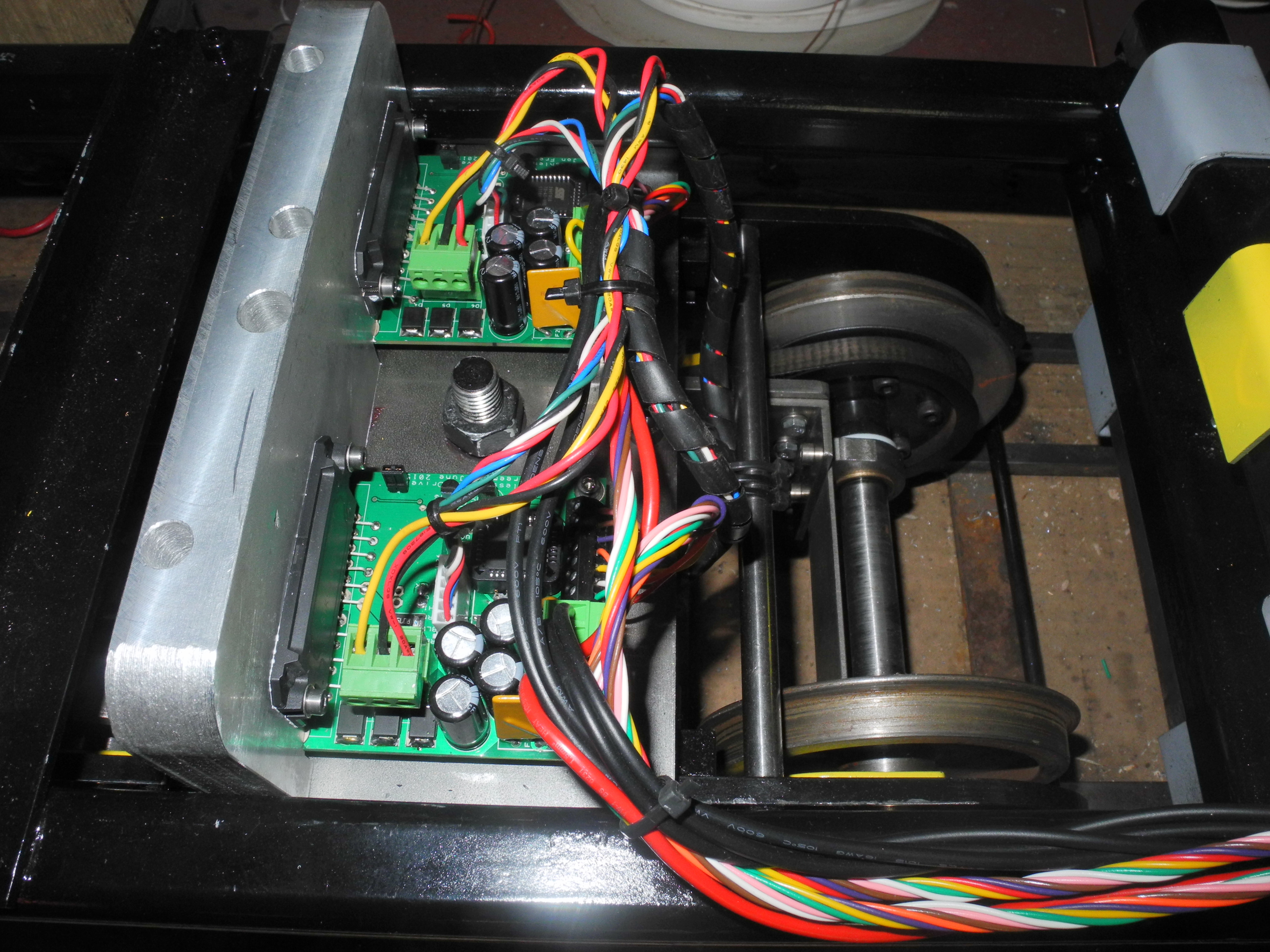
Photo 24 - Two boards above bogie
I had already decided the electronics designed so far was very much the 'Mk I'. One difference with the 'Mk II' will be that the power electronics driving each motor will be on a separate board, not all on the same board as in the Mk I. Not that motor drivers should blow up, but with separate units, a failed driver could be disconnected and the loco run driving three out of four axles, or a board could be swapped in the field.
Progress on the Mk II electronics now proceeded apace. The Mk I was always going to be a prototype, it had earned its keep and much had been learned about brushless motors and how to use them to best effect. I realised there was a simpler way of designing the drive electronics using configurable logic chips, effectively removing much of the burden from the control computer. A board was designed with a 'PWM' (Pulse Width Modulation) input to control motor speed, and other inputs sufficient to implement a full four quadrant motor controller – so that the motor can be driven as a motor, or used as a regenerative brake, in both forward and reverse directions. Photograph 22 shows a bare Mk II board which measures a little under three inches square. The grit-like specks pictured by the tweezers are surface mount components that measure less than one sixteenth of an inch in length. Many fight shy of using surface mount components, but in bright daylight, using very fine solder, the tweezers and wearing two pairs of reading glasses, I can still just about get away with it. Some fine solder wick is also almost essential. Working at this scale almost inevitably means you will manage to splat solder where you didn't intend. Photograph 23 shows two boards under construction. Worth noting, when using surface mount components it makes sense to use both sides of the board, keeping it small, and minimising board cost!
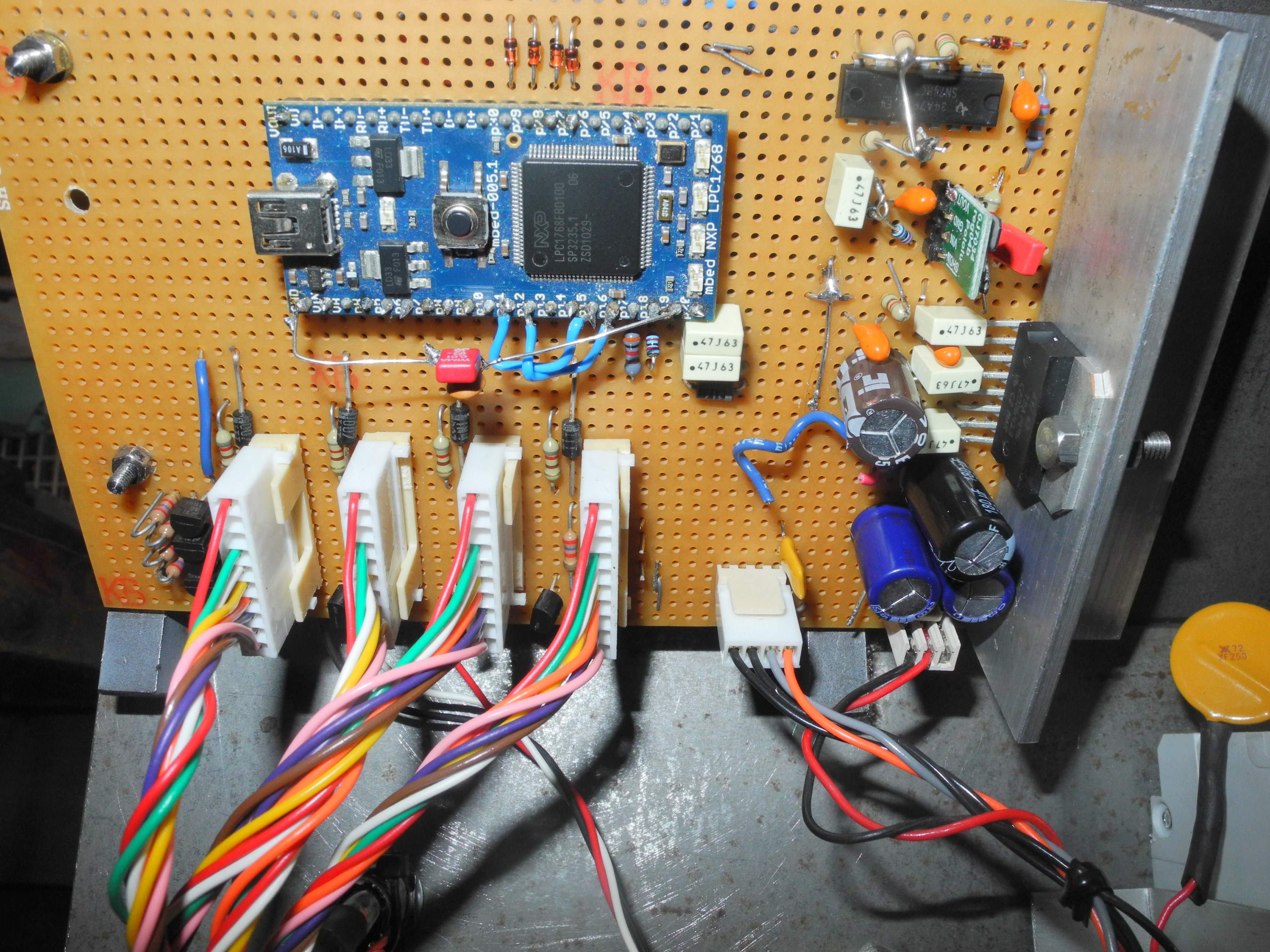
Photo 25 - MkII controller board
As the STK544 motor drive module is rated up to mains voltage, the same board could be used to drive 220V three phase motors with the change of a few component values – electrolytic capacitors rated at a higher voltage. Although designed to drive motors with three power connections, it can also be used to drive a permanent magnet DC motor with two connections in voltages anything up to 300V. Both AC and DC motors can be driven in either direction, both may be used as motors or generators. The only limit is in the case of using motors powered from the mains, what to do with regenerated energy? In the loco, regenerated power is put back into the battery, not so easy putting power back up the mains. A combination of links fitted to two jumper plugs on the board enable it to be set up for brushless motors, permanent magnet DC motors, or three phase AC motors. This means that if for some reason I wanted to swap the brushless motors for PMDC motors, or fit these boards into another design of loco, I could do so easily with minimal effort, other than setting the jumpers correctly. Another jumper is used to swap motor direction. In this design, with the pair of motors in each bogie facing in opposite directions, the motors need to rotate in opposite directions. This is now taken care of by fitting a 'direction' jumper to one motor drive board per bogie but not the other. If the bogie runs backwards the jumper is on the wrong board. This arrangement means the controller doesn't need to 'know' this detail of bogie design. The central controller is still capable of driving the loco in forward and reverse directions using a separate wire carrying the direction signal.
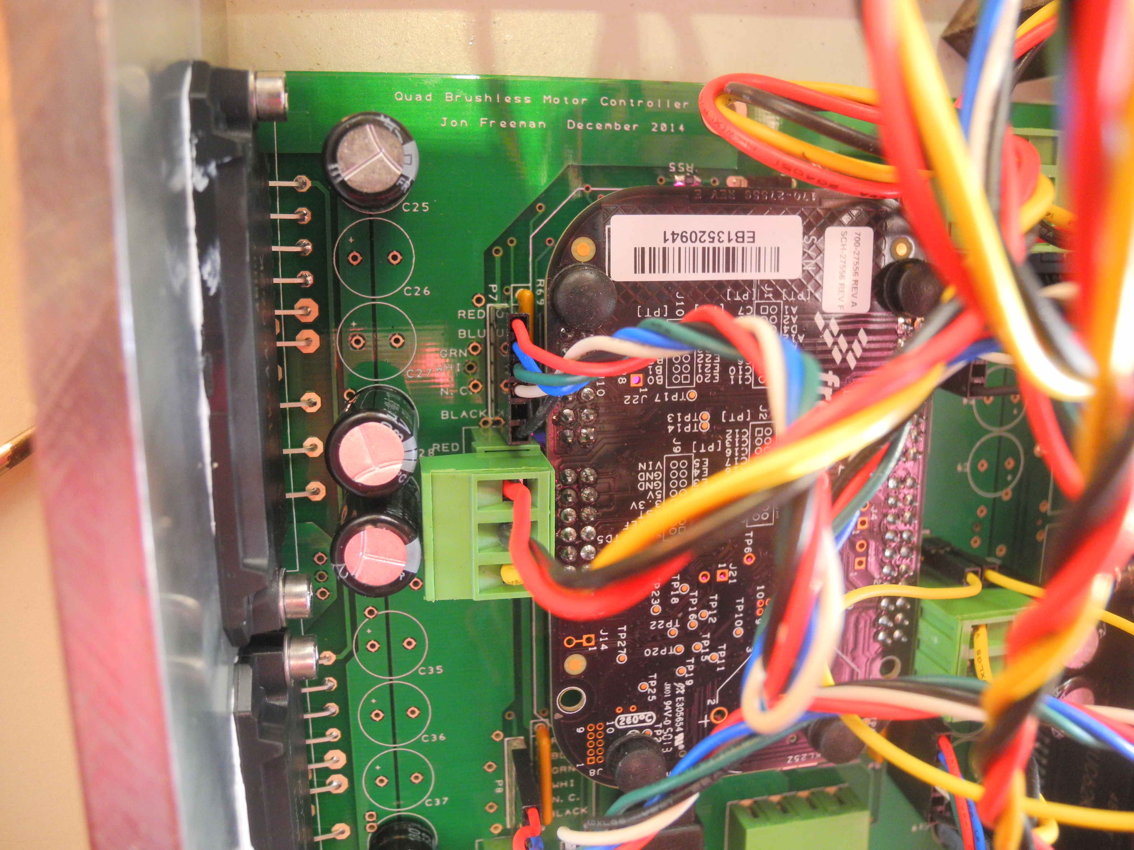
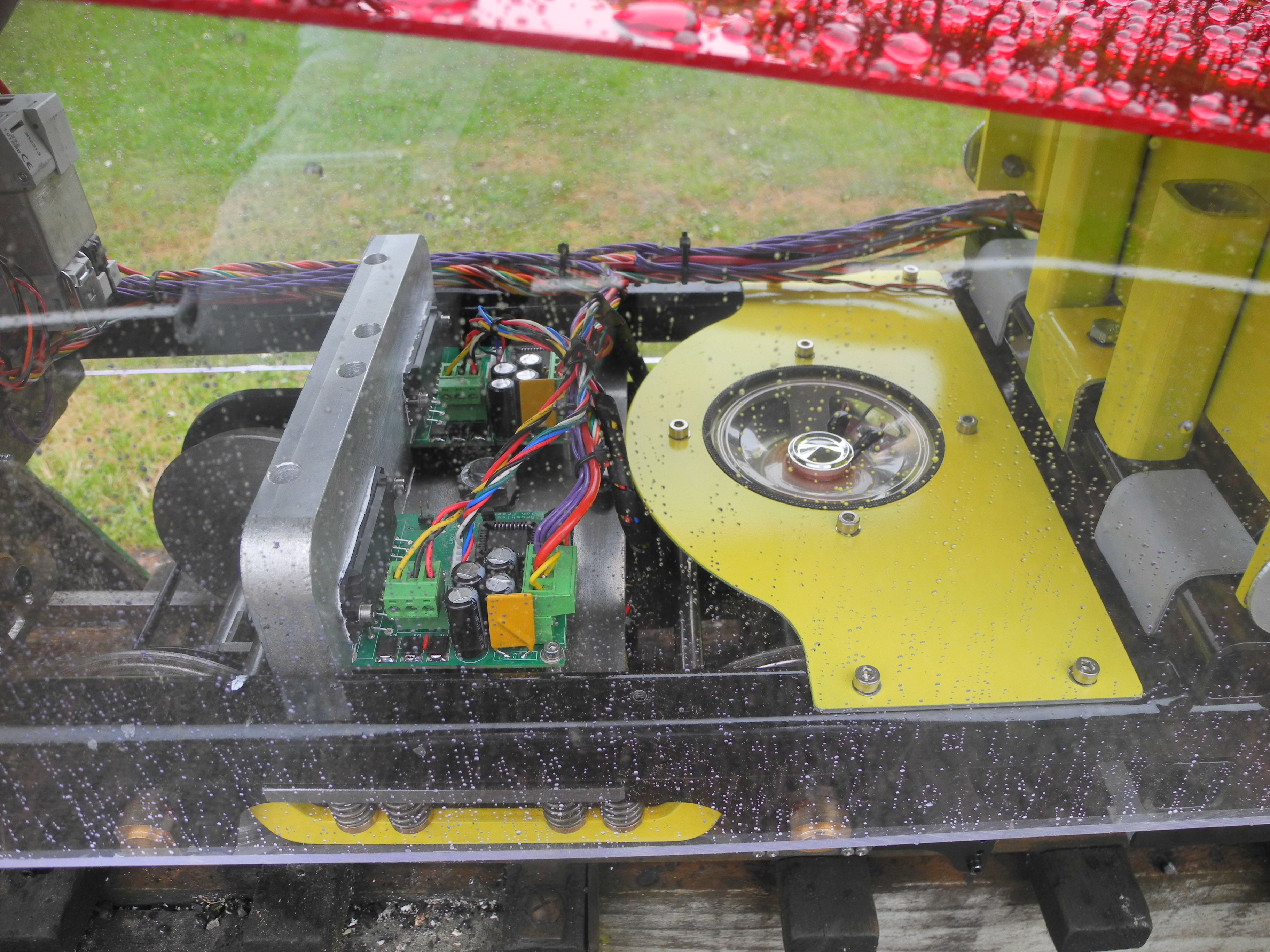
Photograph 24 shows two boards mounted above a bogie in the completed locomotive. Two more boards are similarly fitted above the other bogie, the four boards being connected back to the new central controller, as in photograph 25.
The new central controller started as a 'Mbed LPC1768' computer wired to a quarter-VGA (240 by 320 pixel) LCD display (something I had left over from a previous project), and is cobbled-up on a piece of matrix board as I could not justify the expense of a third printed circuit board. This computer is very similar to the KL25Z used in the Mk I, and the plan was to come up with some kind of joystick arrangement to wire into it to be used as the torque or speed control and brake. Looking for something more reliable than a carbon potentiometer, various exotic devices were looked at to provide some position information to the controller. A leading contender was a rotary encoder from RS Components. This used a magnet mounted on the end of a shaft and was capable of reading absolute angular position to an accuracy of better than one tenth of a degree, and is designed to measure shaft angle at speeds from zero up to 12,000RPM! The data sheet looked promising, a device was ordered. Upon arrival it was apparent a tiny 5 pin connector was required – RS could not supply, and it was judged too small to try soldering wires to the pins. Back to the drawing board, and while thinking about the complexity of a mechanism with springs, dampers, levers and pivots, the thought dawned of using the touch screen on the LCD display instead!
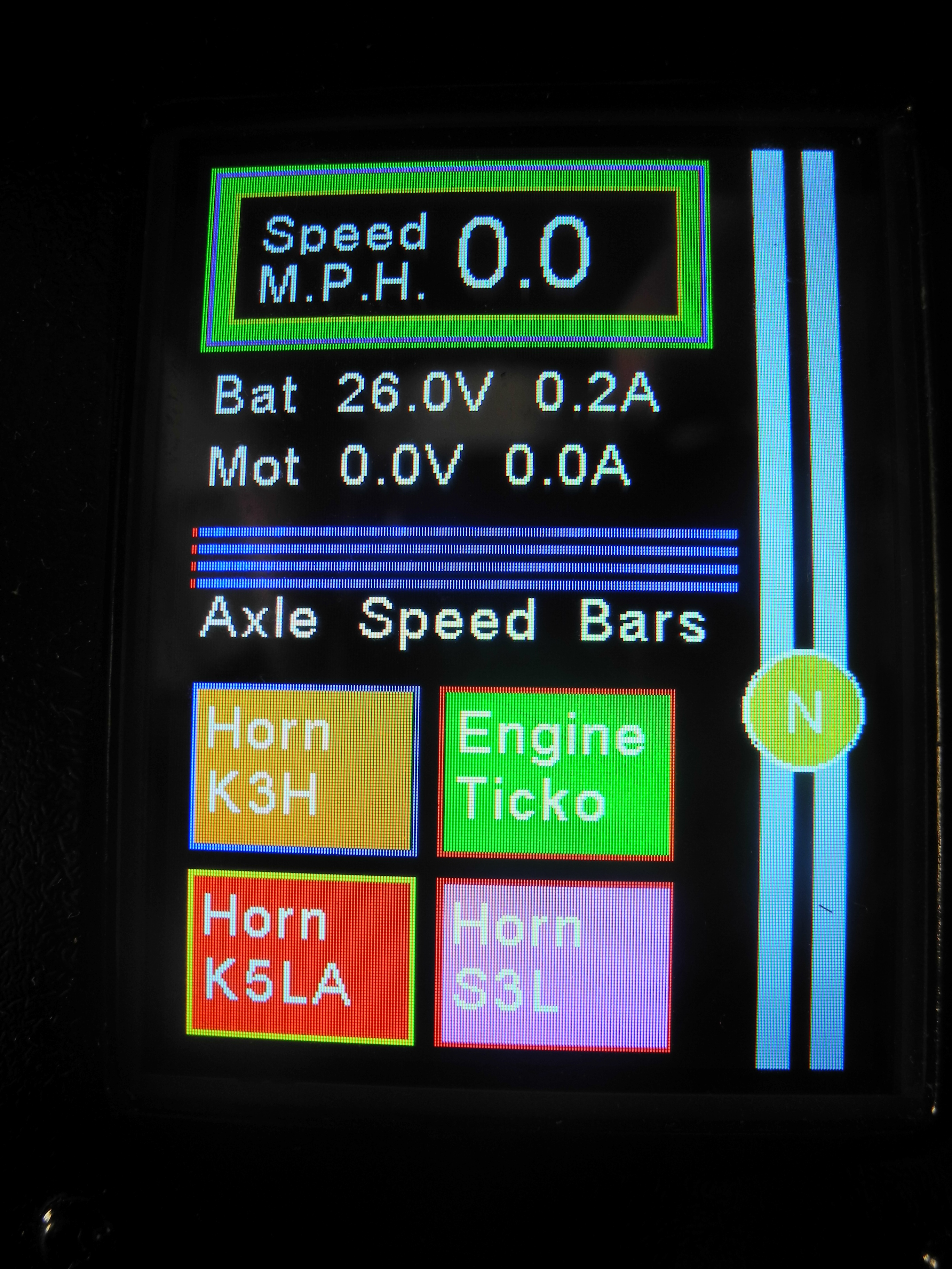
Photo 26 - Display and touch screen
Like Topsy, it just grew. Once the touch screen was in the pot, 'buttons' were an obvious possibility, and at least one of these was needed, as I was told, for the horn! Ah! Sound. Another new requirement. An audio amplifier chip and loudspeaker were sourced, and five tone generators were programmed into the controller. This enables imitation of any air horn with up to five horns, as well as many other daft sound effects. A fair imitation of a diesel ticking over can be made by playing 3 or more discordant low notes together.
The display is used to show as much information as needed - see photograph 26. The speed readout is useful for observing the 6MPH limit on the club track. Each motor board feeds back one pulsed signal indicating motor speed. The loco speed is calculated using averaged motor speeds. The four bar graphs below show individual axle speeds. This is useful to check for wheel slip, and would also show if something jammed or a drive belt failed. There are two voltage and two current readings shown. The battery voltage is measured directly, the battery current is measured using a Hall effect current sensor circuit. The displays of motor voltage and motor current are calculated as there is no simple way of measuring either, and are there for my benefit while I tweak various algorithms in the control software. The motor voltage should never be higher that battery voltage, but by using PWM control the motor current can be very much greater than the battery current – not paying sufficient attention to this had previously led to letting the smoke out. The four buttons shown currently operate sound effects – a choice of three American or Canadian loco horns, and 'Engine Ticko', the button is not wide enough to take 'Tickover'.
The slider to the right of the display is the driving 'joystick'. In photograph 26 it is shown in the 'N' for 'Neutral' position, the motors are free to spin, not being driven as motors or brakes. Touching the slider and moving the finger drags the circular spot up or down with it. Downwards applies progressively more regenerative braking effort. Taking the finger away leaves the 'brake' where it was last touched. Moving the finger upwards from 'N' causes progressively more torque demand – this is a torque demand control rather than a speed control and as such, has a characteristic not dissimilar to the car accelerator pedal. Club rules insist electric locos have a ''dead man's'' function, that is to say with hands off the power should be cut. For this reason the software was designed such that taking the finger off when driving causes the spot to gently glide back to 'N' and the loco should glide gracefully to a halt. A lever, spring and damper implemented in software!
For more detailed coverage of the electronics, please refer to
www.jons-workshop.com
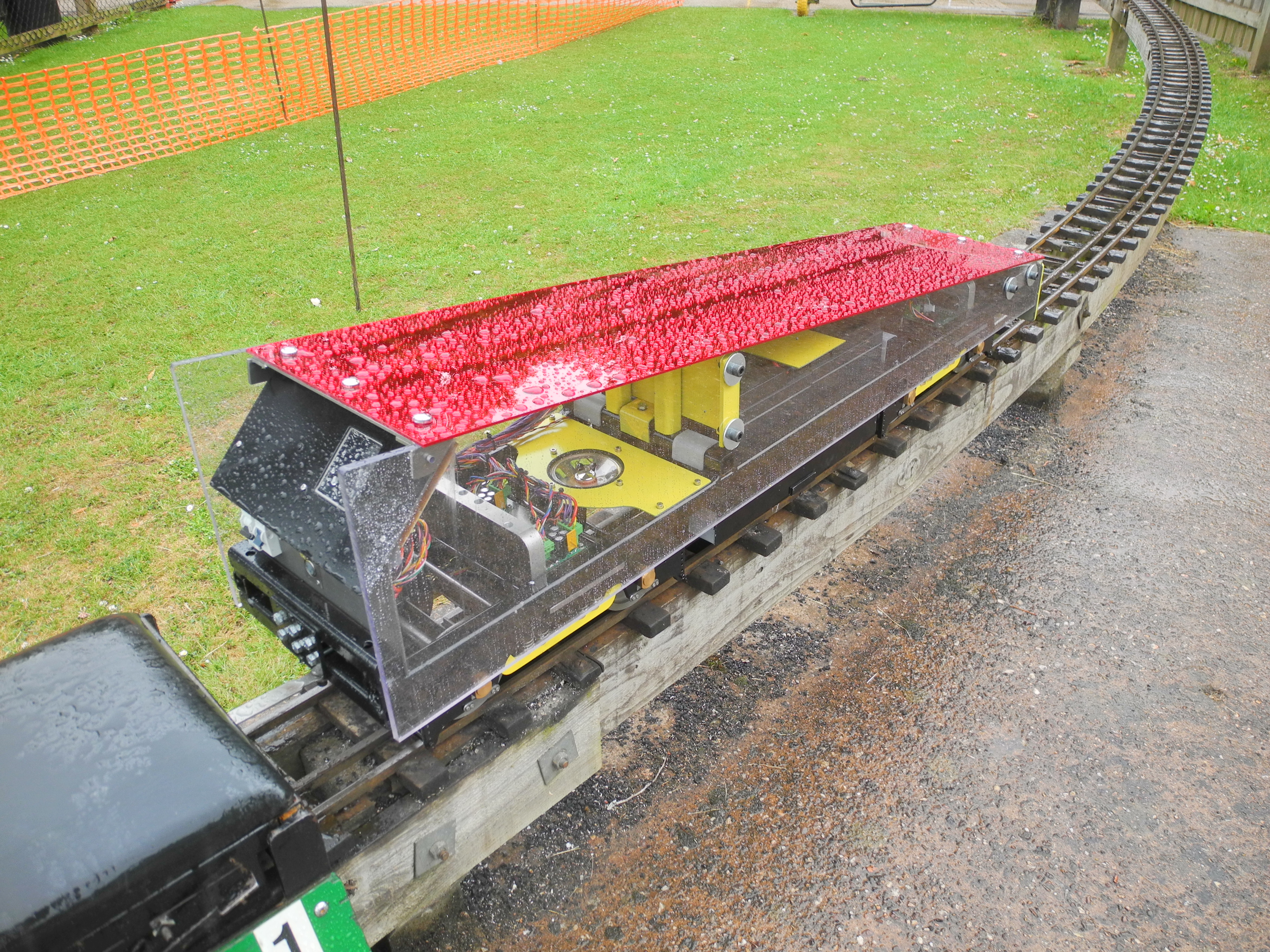
Bodywork
Photo 27 - Looking through the wedge
With the mechanics completed and the Mk II electronics tried and tested, only a protective paint job and body shell remained on the “To Do” list. A fellow club member kindly gave me a set of CAD drawings for some very impressive Hymek body shells he had built in a larger gauge. This was far more work than I had time for, and too many tweaks would be needed to fit a Hymek body to a loco chassis that was basically not very Hymek-shaped to start with. Similar thoughts applied to the idea of dressing it up as any other kind of lookalike, and so it was decided to make it look like nothing that came before, and to do something quick and simple. The highest part is the control panel and there is not much to be seen towards the front. This suggested a triangular, or wedge shaped body shell. This was made using 8mm polycarbonate sheet sides and a perspex mirror top. At the club track in Vivary Park, Taunton, it is known as “The Wedge”, or “The Edam Wedge”. Photographs 27 and 28 show the finished “Wedge” at the park.