The entry level manual vertical milling machine will have a handle to move the table to the left and right – the 'X' axis, another to move it forward and back – the 'Y' axis, and a handle, lever or some other means of changing the vertical distance between the tool and the table – the 'Z' axis.
While much good work has been done with such basic machines, many a machinist would have longed for a machine fitted with a 3 axis DRO (digital readout). This would have helped reduce the number of mistakes made by losing count of how many turns of the handle, or errors in the addition and subtraction of dial graduations, backwards or forwards.
The next wish - a power feed on at least one of the 'X' and 'Y' axes. This would free the machinist from having to stand still for long periods turning a handle at a constant, slow speed. An ideal manual vertical mill may then be thought of as one with a three axis DRO and a power feed on each of the X, Y and Z axes. A CNC machine can be used as if it were this 'ideal' manual machine, but it is capable of far more. Methods used for manual driving of CNC machines vary. Some machines have the same handles found on their manual equivalent, in others the handles give way to buttons or keys on a keyboard. Most CNC machines have a 'MDI' or Manual Data Interface enabling direct command keyboard entry – a hugely useful feature! In short, there is really nothing that can be done with a manual machine that cannot be done with a similar CNC machine. However the CNC machine opens up possibilities the manual machinist can only dream of.
Boiler Bushes – a Case Study
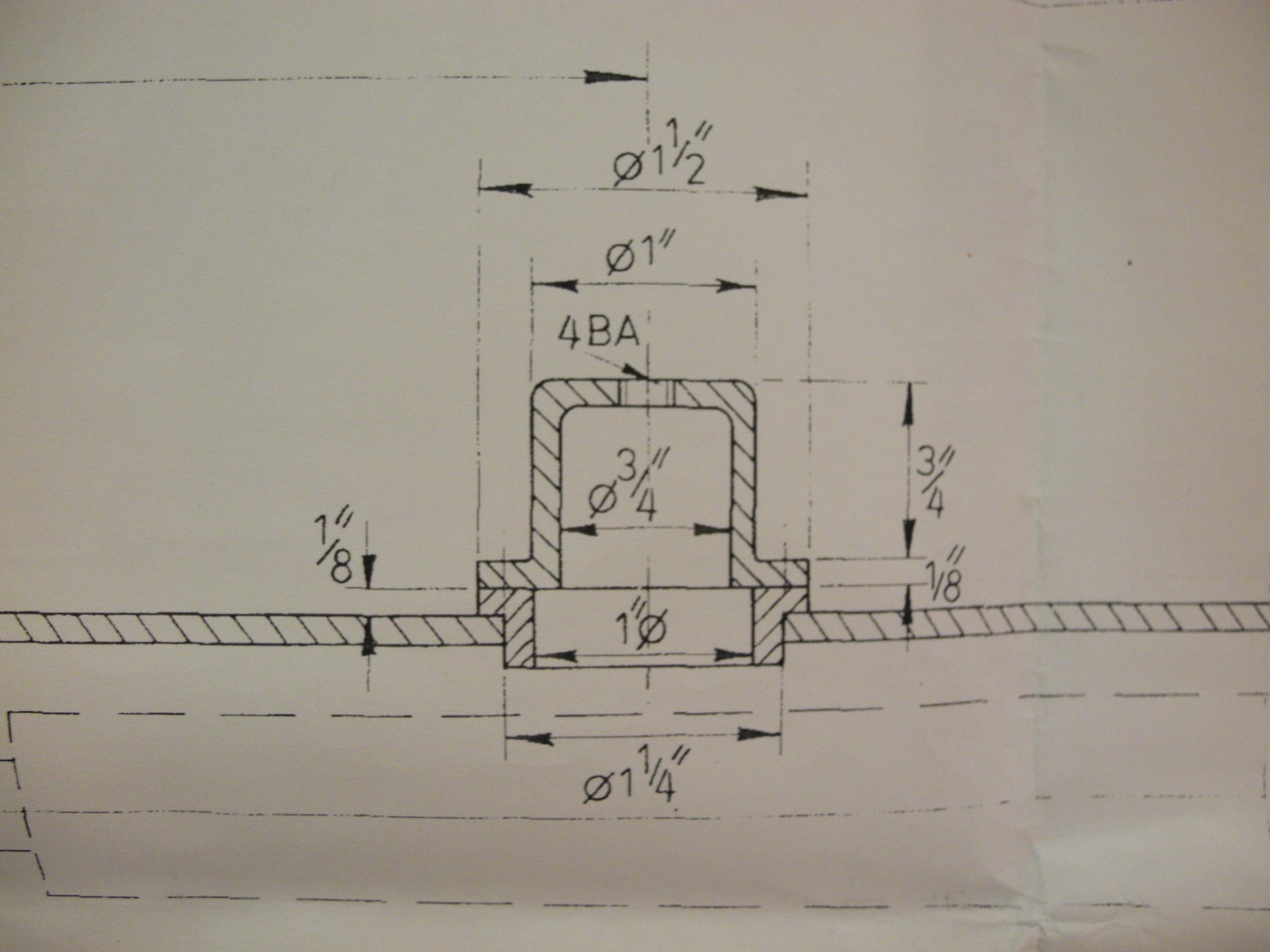
Fig 201 - Old Boiler Bush and Inner Dome Drawing
Fig 201 shows a sectioned view of a 5” gauge locomotive inner dome and boiler bush. The drawing dates from some time around the middle of the last century. Sadly it's too late to give the designer a call to ask questions, leaving us to speculate. Why is an inch and a half diameter bush turned down to pass through an inch and a quarter hole? The designer probably had some inch and a half bronze, and he probably had an inch and a quarter drill, but looking at the indicative lines vaguely suggesting where the screws might go to hold the inner dome to the bush, there's not much metal to drill the tapping holes into before the drill breaks through into half metal, half fresh air. This is to be avoided for several good reasons. For a start there is the increased risk of breaking a drill or worse, a tap (because removing the broken part may prove well nigh impossible). Bad enough if drilling and tapping the bush before soldering to the boiler barrel, but a disaster to break a tap in an almost finished boiler! Should these be drilled and tapped before of after soldering?
Although the drawing shows the flange sitting snugly on the boiler, of course there will be only two points of contact between the flat flange and curved boiler (see Fig 208). The flange therefore, contributes nothing to the strength of the silver soldered joint when the bush is fitted to the boiler. Considering what the flange is there for, apart from somewhere to drill and tap the fixings, it has only one other purpose - to stop the bush falling into the inside of the boiler during assembly. How much bigger than the hole does the bush need to be?
With so many things that can and do go wrong with complex projects such as miniature steam locomotives, as engineers we owe it to ourselves to cast a critical eye over items such as this before slavishly copying methods from bygone centuries, and to eliminate potential problems wherever possible. It might be a fair bet that our designer also had an inch and a half drill (just a touch too big) but did not have a one and seven sixteenths inch drill – drills in the larger sizes have always been eye-wateringly expensive. If he had, he could have drilled the boiler this size and turned less metal off the bush to match with advantage that drilling and tapping for the inner dome fixings would avoid the potential break-through peril identified and still left enough to locate it for soldering.
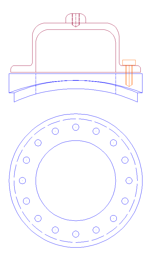
Fig 202 - Generic Boiler Bush
A suggested new improved bush design is shown in Fig 202. This illustrates a flange profiled to hug the boiler profile (the part that protrudes through the boiler shell is also shown as being profiled, although this may not be necessary in many cases). No dimensions are shown as this is a generic drawing for items of this type. This drawing is intended as a library item to be imported, stretched, scaled and dimensioned to suit particular projects as they come along, but note the relatively increased diameter of the part to fit through the boiler barrel hole so ensuring clean solid metal around and below all the drilled and tapped fixing holes.
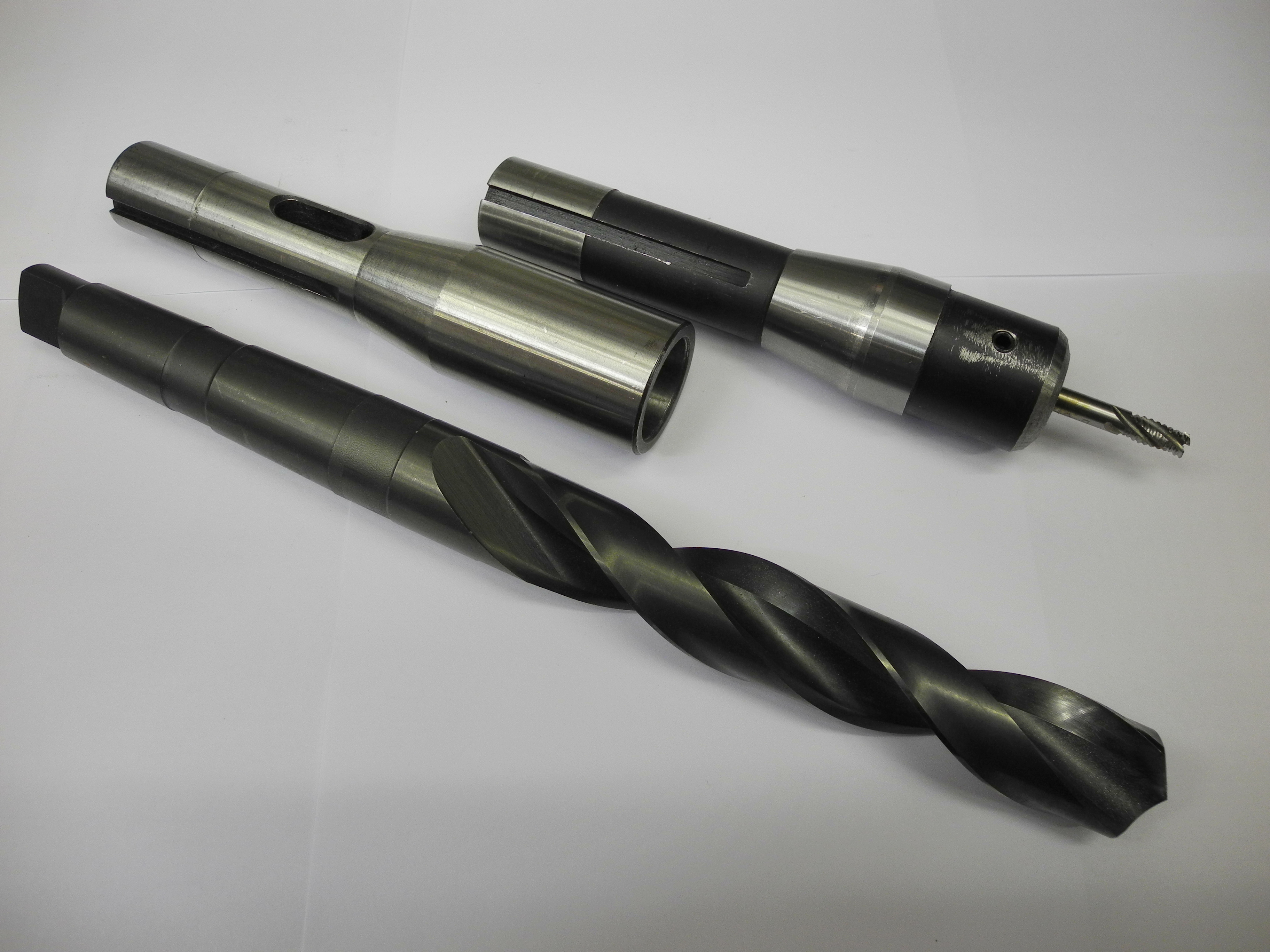
Fig 203 - Alternative hole making tools
Drilling large holes through the side of copper boiler barrels is no job for the faint hearted. Advice on tasks such as this may be found elsewhere including tales of grinding drill edges to negative rake angles, use of various unlikely sounding lubricants, drills catching or digging in, how to hold the work firmly enough and what might happen otherwise – it can all get quite scary. Using a large drill seems one obvious method for hole making, there are others. Fig 203 shows a choice of tooling that could be used to cut a large hole, a 6mm ripper cutter, and a 25mm No.3 Morse taper shank drill and sleeve that will just about fit the Sieg KX3 machine (Fig 204). This setup has been used for drilling soft wood but it was not tried for drilling steel as the KX3 spindle will simply not deliver enough torque at the low 130 or so RPM required to drill steel. The manufacturers specification claims drilling capacity up to 20mm for the KX3 machine but without stating through what. For woodwork that's probably about right, but for drilling steel, experience indicates that 8mm or possibly 10mm is about as large as it is sensible to try.
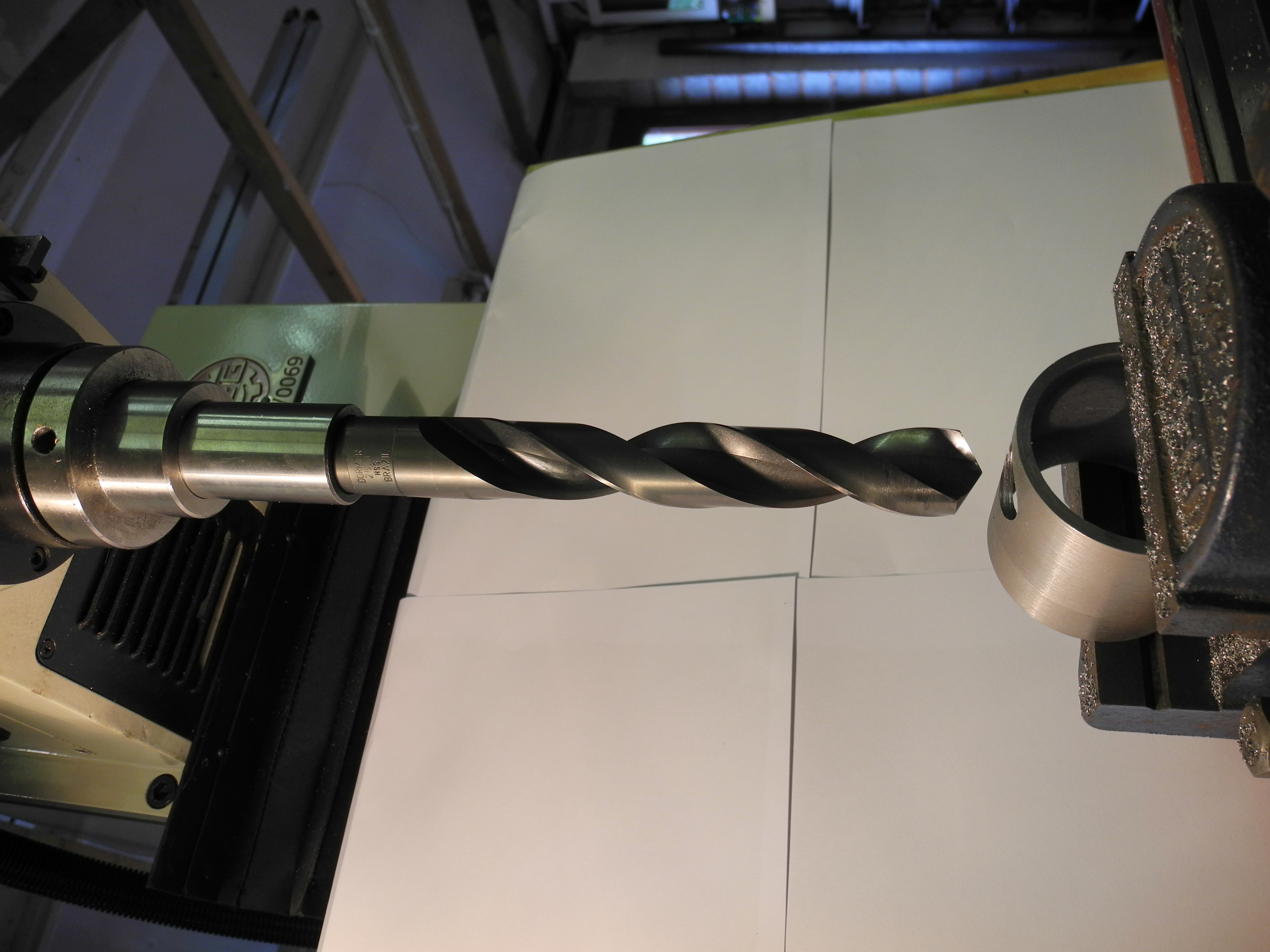
Fig 204 - 25mm drill Good for wood but not steel on a KX3
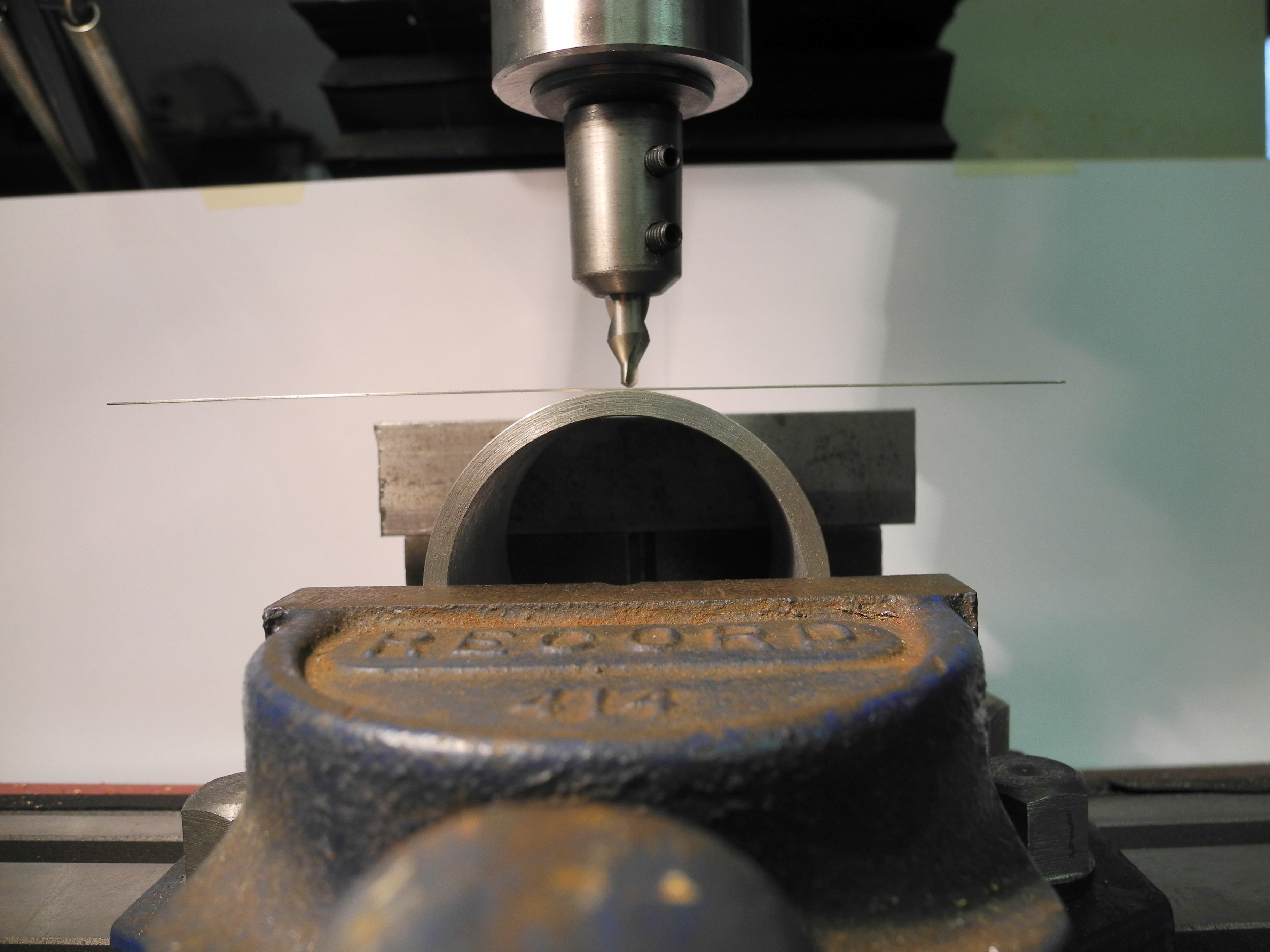
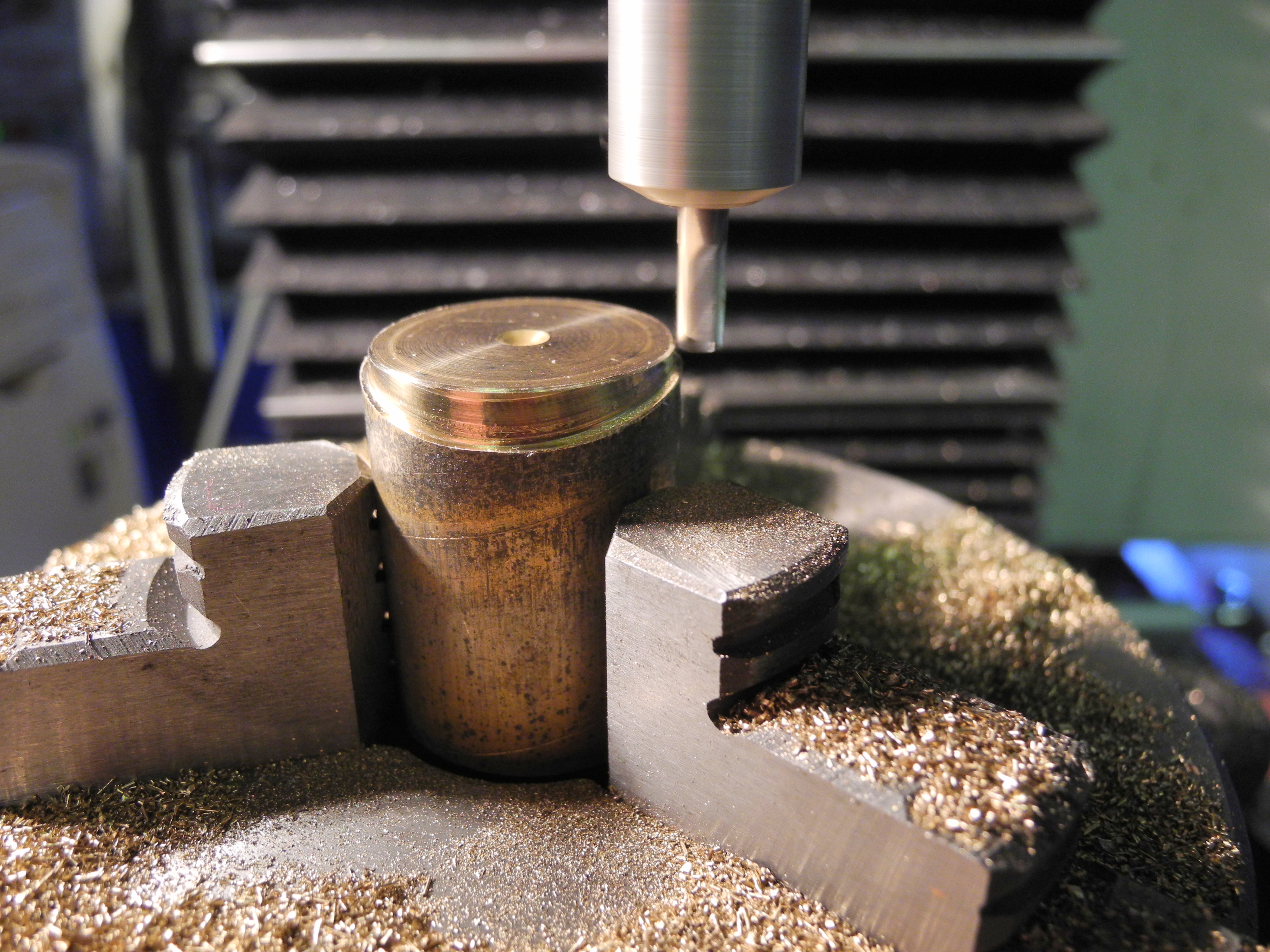
Fig 205 - Finding the centre line
However, the CNC mill owner needs no expensive large drills for making shallow holes such as this as we have at our disposal the means to make holes of any size or shape we wish. Drilling a large circular hole may be achieved by simply programming the machine to move a small, rotating end mill down in a slow spiral motion. Fig 205 shows a tube (steel scrap used for demonstration purposes) clamped in a machine vice mounted on the KX3 machine table. A quick and easy method for finding the centre line is as shown. Moving a pointed, centred object, such as a centre drill, to be close to centre by eye, carefully lower the tool to lightly pinch a thin flat piece, a steel rule in this example. Move the table slowly left and right, the tool is centred (close enough for our purposes) when the thin flat is horizontal – this works well so long as the work piece is round!
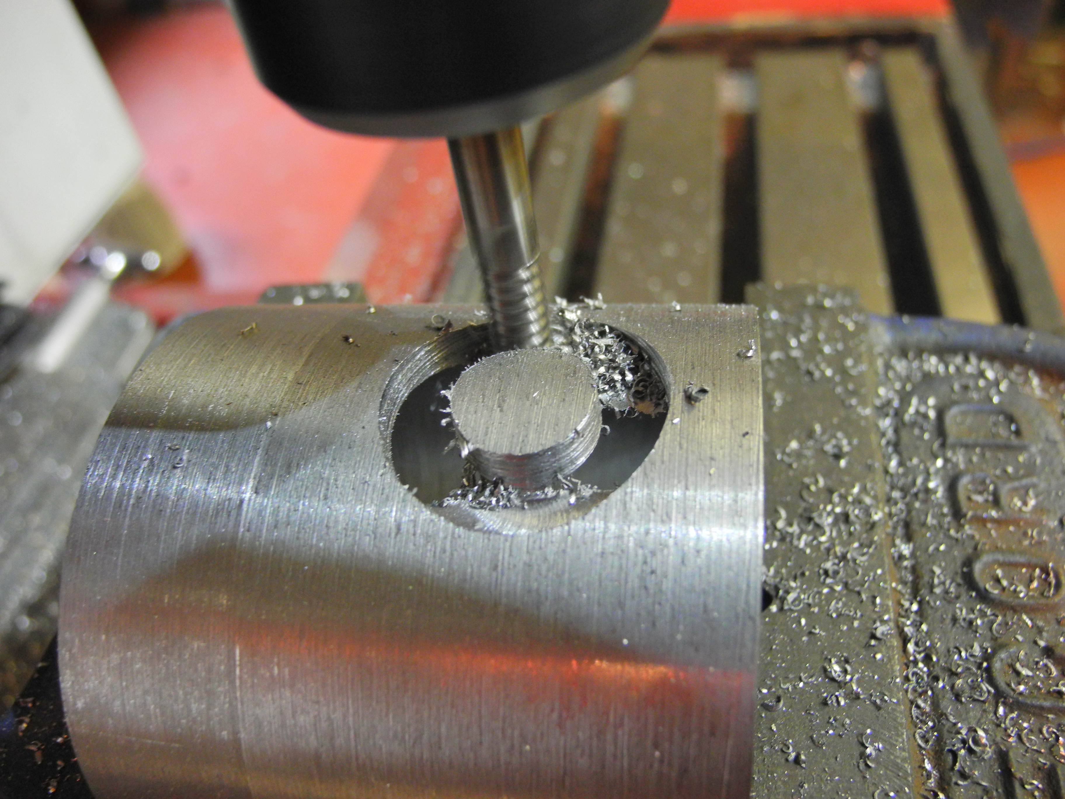
Fig 206 - Small milling cutter large hole
A simple programme was written to move a 6mm ripper cutter down through four turns of a spiral to cut the hole as seen in Fig 206. This was not at all traumatic compared to using large drills, the machine was being run well within its capabilities, and better control of hole size and shape was obtained. For precision work, one method would be to rough out the hole a little undersize, and then increasing the hole diameter in the programme to the final size for a light finishing cut – CNC effectively supplying the infinite set of drills of all sizes! The ripper cutter does not give a smooth finish but this could be advantageous for silver solder penetration.
Making Bushes – Traditional method
Fig 207 - Turning - the old way
Fig 207 illustrates the old traditional method of boiler bush manufacture, turning a shoulder so that the bush fits into a hole in the boiler barrel to a depth sufficient to make a good silver solder joint all around, fig 208 shows the bush trial-fitted and the inevitable mismatch between flat flange and curved tube surface.
One difficulty is in soldering bushes of this type so that the bushed fittings all end up pointing in the same direction – a pair of safety valves on top of a locomotive pointing in slightly different directions looks quite ridiculous! The temptation is to make the bushes a tight fit and take care in alignment before soldering. This is not a good idea however as a clearance of around 0.1 to 0.2 millimetres should be allowed for the solder to flow properly and penetrate all the way around the joints.
Fig 208 - Old style bush trial fitted
Making Bushes – a CNC method
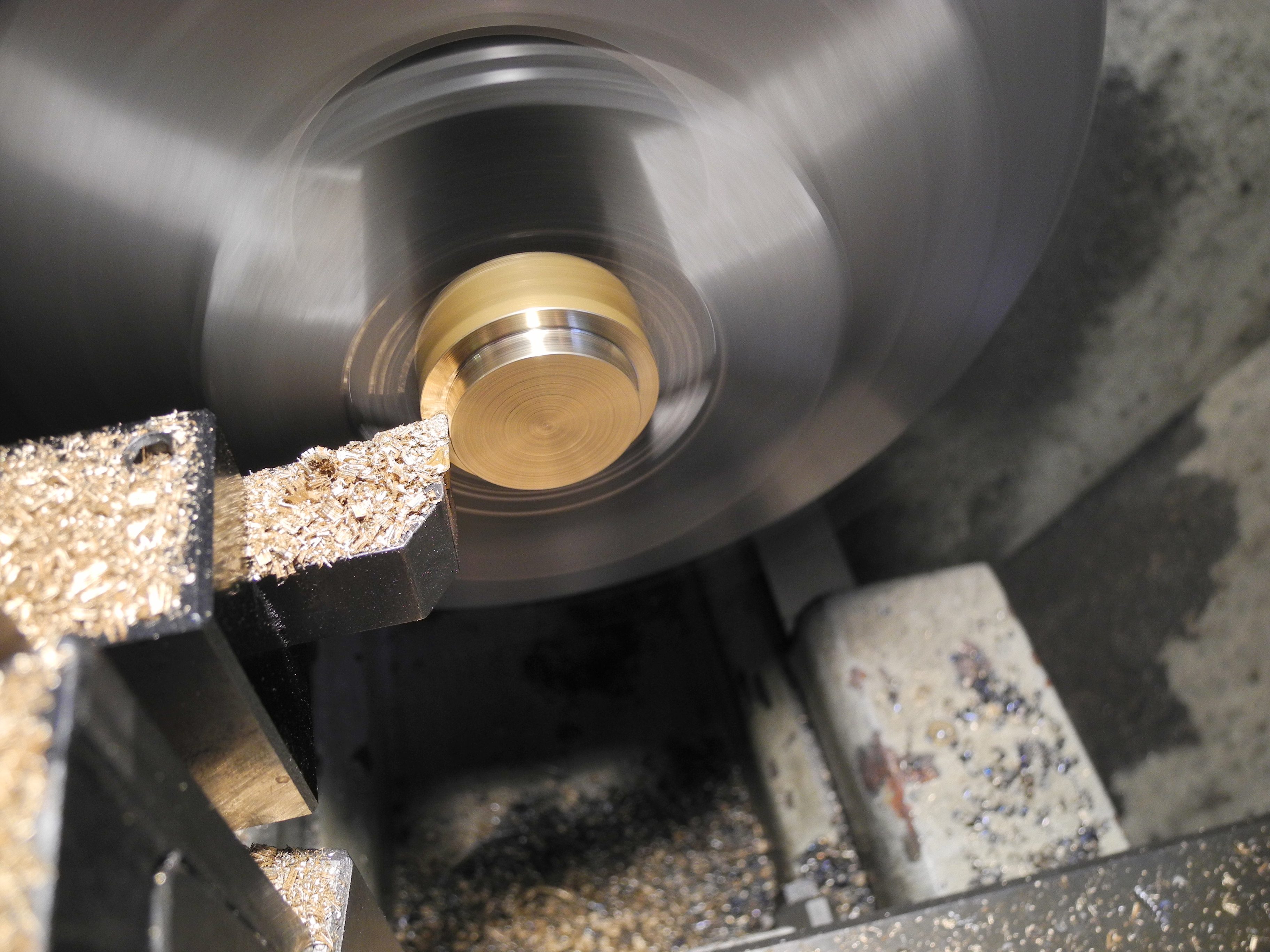
Fig 209 - Machining the CNC way
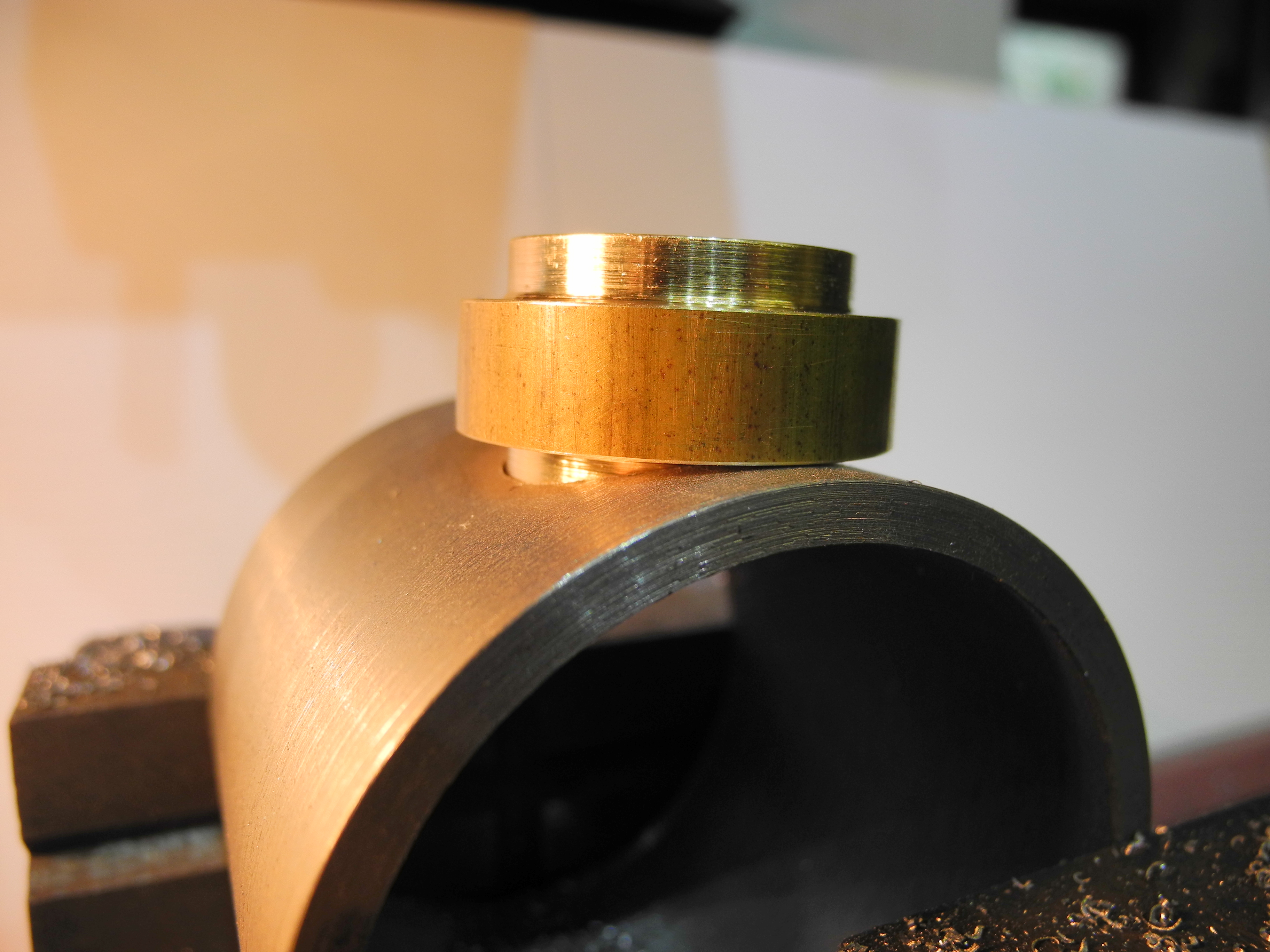
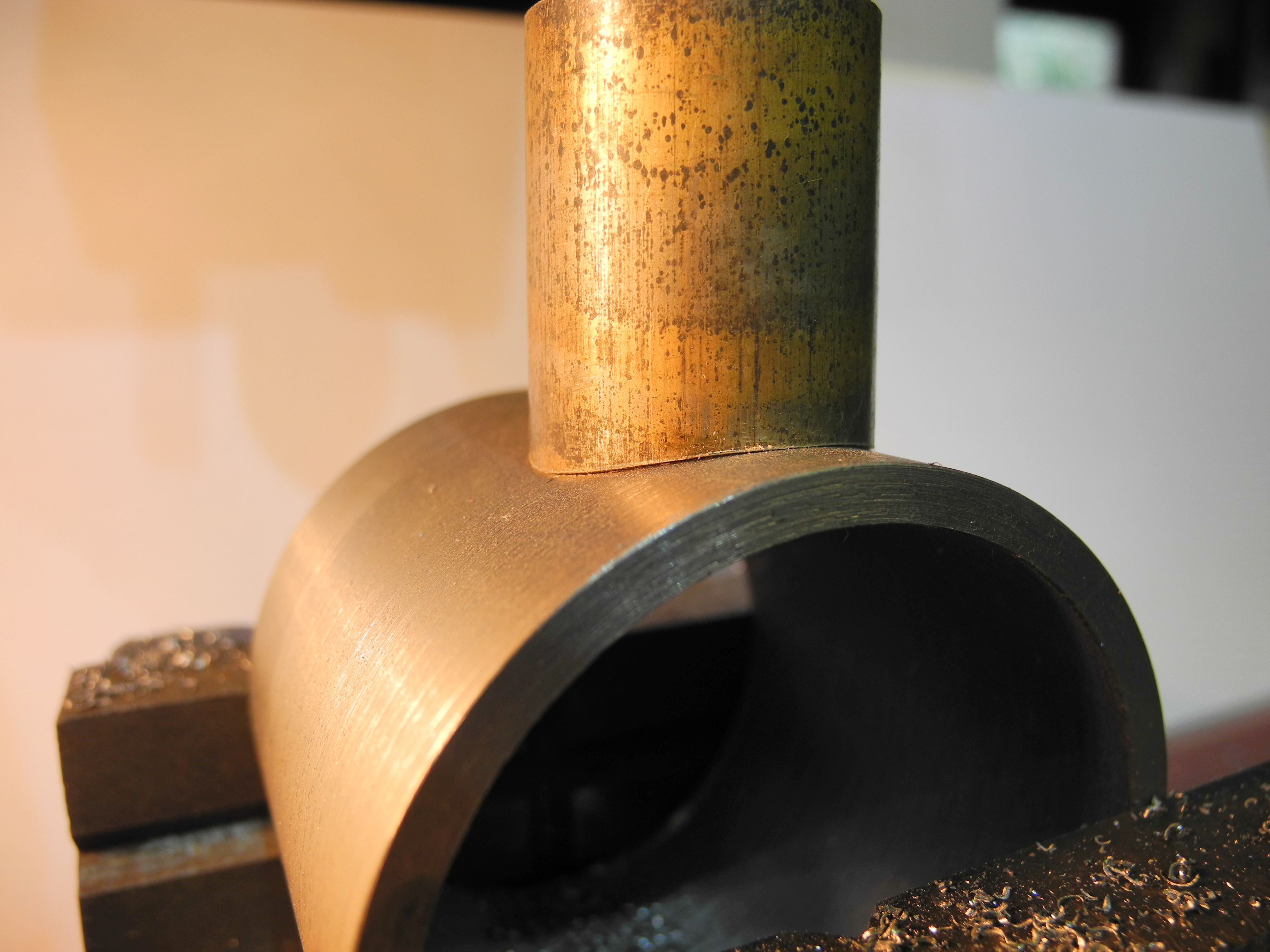
We can make better bushes than this using a CNC machine as illustrated in Fig 209. Here a 3 jaw chuck is clamped flat on its back to the CNC milling machine table and a 4mm end mill, running at about 2000 RPM, is moved slowly under programme control, in an undulating circular motion around the bar stock machining the boiler-hugging profile. This fitted our mock-up boiler as shown in Fig 210. Having put in a little thought and planning, a bush is machined that sits properly on the curved surface. This makes it almost impossible to solder at the wrong angle, increases the area and strength of the solder joint a little, and the CNC programme to do this boils down to something quite surprisingly simple.
Fig 210 - A snug fit
First thoughts about writing CNC programmes
Looking at work covered so far, a CNC programme is needed to cut a hole in the barrel, another programme is needed to cut the undulating flange, and optionally, a third programme to scallop out the underside of the bush could be written. It is worth noting the similarities between the first two programmes. Both involve moving the tool in a circular motion with height changes. There may be scope to combine both programmes into one, or at least to write, test and prove one programme and then use that as a good base from which to build the other.
What does a CNC programme look like?
A CNC programme, or any other type of computer programme for that matter, is a list. A well written programme is list of executable instructions, interspersed with sufficient useful plain language comments to inform the reader what is supposed to be going on at all stages, written in a plain text file. When the programme is run, the computer starts reading the file from the top, gathering information, ignoring the comments (which are exclusively for benefit of the human reader), and executing any instructions it finds. This happens in order from the top of the file to the bottom, or until an instruction to stop, end, or do otherwise is encountered. A programmer needs only a computer and simple text editor in order to create CNC programme files.
Avoiding the temptation to leap straight into machine-moving metal-cutting programme codes, a consideration of what makes good programming practice will pay dividends, helping the process of devising safe, robust and useful programmes.
Good Practice – Programme File Organisation
Many older CNC machines and systems have primitive filing systems for saving work files. There are still many machines in use in industry today that use small floppy disks for file saving. As well as being low capacity, these have serious limits on the names you can choose to save your work files, typically limiting name length to eight characters. This is not helpful as programme names this short can not contain many clues about what a programme is, or what it is for. Because of these limitations, many an experienced CNC machinist has accumulated boxes full of floppy disks, each with a few 'useful' programmes on them, yet they will choose to write new programmes from scratch rather than spend time rummaging through them all in hope of finding something usable! Thankfully technology has moved on and there remains no excuse for such chaotic and inefficient file management. Cheap USB memory sticks each have the capacity of several thousand floppy disks, and even a cheap computer hard drive has far more capacity again. File names of enormous length are now possible so making it perfectly sensible to use file names describing what programmes are for. Files may also be organised into different folders or directories for different jobs, keeping all the files for a particular job in one place perhaps. Making it easier to find and identify programmes encourages reuse of old programmes rather than keeping on reinventing the wheel. There is nothing special about reusable programmes, but writing a programme with future re usability in mind seems a sensible idea.
Good Practice – Making Code Reusable
Thinking about a programme to mill circular holes, a sensible and helpful programme file name such as “circular_hole_miller” could be chosen. This is a good start, but thinking about design for re usability, a “generic_circular_hole_miller” programme could be written for use any time we want to mill a circular hole. The set of user-supplied information needed by a generic programme to mill out a some-sized hole somewhere is self-evident : -
	Hole size
	Hole depth
	Hole position X, Y, Z
	Tool size
	Tool feed rate
	Tool RPM
There is no need to know, for now, how the programme uses these user supplied numbers. It is possible, or likely, that each number may be used in a number of places throughout the code. A programme could be written such that these numbers are written into the code in each and every place where needed, and this may be a reasonable strategy for a very simple programme. However this does not encourage re usability or reliability. In addition, as programme complexity increases it becomes increasingly impractical to keep track, and an increasingly unattractive prospect to search through and edit the programme in order to reuse it.
Good Practice – Programme Structure
A better method, introducing some structure and aiding re usability, would be to group all the user supplied information together near the start of the programme file, in an area computer programmers would probably name the “User Interface”. The rest of the programme would then be written to read what it needs from this user interface. In this way, effort is applied to writing the programme once. Thereafter, reusing for another hole in another place on another day becomes a simple matter of tweaking the numbers in the user interface, saving the file, pressing the 'Start' button, standing well back and enjoying.
The user interface is also the obvious place to include as much useful plain language comment as would ever be needed to guide another user into being able to use this programme successfully. In the previous article, a safe, two line programme in plain English “pseudo-code” was developed : -
  STOP
  END PROGRAMME
It does not do anything useful, but at least it stops anything bad happening and ends safely. Expanding this to include a user interface gives us : -
  Programme File Start
  User Interface Start
  … Put descriptive comments here
	Programme Title :
	Author :
	Date :
	Why was this programme written?
		...
	What does the programme do?
		...
	Any other useful information
		...
… User defined task related numbers go here
	Assign users numbers to memory
  User Interface End
  Programme code goes here
	...
  STOP
  END PROGRAMME

  Programme File End
This represents a reasonable first stab at the creation of a structured, safe, reusable programme. Using this as a template, in the following article this will be developed further into a fully working CNC programme conforming to the dialect of the “G Code” programming language recognised by “Mach3” CNC software – as used to drive the Sieg KX3 machine used in the examples above. Keen readers may wish to proceed into downloading and installing Mach3 software now, although this will be covered at the beginning of the next in the series.