The purpose of these articles is to look at entry-level home workshop CNC and beyond into ways in which modern equipment, tools and methods more generally, may help improve our productivity. There are reasons to be cautious before buying CNC machine systems, the life expectancy mismatch between the electronics and mechanics being one. What are you going to do with your still 'as new' machine in a few years when the electronics breaks and is no longer repairable? We'll look into this next time, when by analysing the computer, electronics and software systems, we can explode a few myths and look at alternative means of driving the machine - moving away from the ever shifting sands of the 'Windows' PC platform is worth a look.
Fitting a DRO to fit to a manual machine is a safe bet for improving productivity, possibly as much as could be achieved with CNC. It rather depends on the work you do. If a scale or DRO display breaks, there's likely to be something available to get up and running again without having to replace the lot.
Using 'free' software, CAD and spreadsheets, can aid productivity greatly, your investment is in time taken creating your work files. Keep copies safely in several places other than your main computer (memory sticks or the 'cloud') and your investment should be safe. With care and planning, your work should still be usable when the next generations of CAD, computer or other software come along.
Building a Locomotive - A Mix of Old and New Methods
Locomotive designs and paper drawing sheets – Oh dear! Depending upon your choice, these may be copies of hand-drawn sheets prepared up to a century ago containing a cocktail of errors, most of which have been known about for decades yet nobody has corrected! The 'Frame' and 'General Arrangement' drawings between them reveal many holes through the frames, but not all, some of which might even be shown as the right size in the right place! Often the designs were serialised in the Model Engineer, the designer may have worked by 'making it up as they went along' (print deadline pressures!) and the remaining holes identified in later parts were never back-annotated. Brackets and other parts made later could be fitted by clamping into approximate position on the part-assembled chassis, lining up by eye while at the same time trying to get it the same height and distance from the wheel as the one on the other side, and drilling through using hand tools – a horrible and inaccurate way of working! We can do better, more accurately, and save time by investing the time it takes to find and check all the hole positions first, and then drilling them all in one session.
CAD – Spending Time to Save Time !
Unlike hand drawing, CAD drawings are created to any degree of accuracy you need. When looking to improve on our ancient 2D paper plans, a 2D CAD costing nothing appears the way to go. 'AutoCAD LT' is a 'reduced features' edition of industry standard 'AutoCAD', and quite sufficient for our CAD requirements. Several 'AutoCAD LT' lookalikes may be found today, downloadable and usable at no cost. As with all software, the market moves quickly and your own internet search for “Free 2D CAD” is recommended (currently in use here – DraftSight from Dassault Systems).
When choosing a 2D CAD system, check that any work files you create may be saved in popular 'Industry Standard' formats, suggested are AutoCAD standards .DWG and .DXF. These are the formats laser cutting firms tend to work from, and may also be compatible as input files for CAM (Computer Aided Manufacture) software. Save your drawings in both formats, and be aware that formats evolve over time. It is easy to save a file from one CAD system in a format that's too new to be read by another. You may want to change CADs without losing all your work!
Ways of Working with 2D CAD
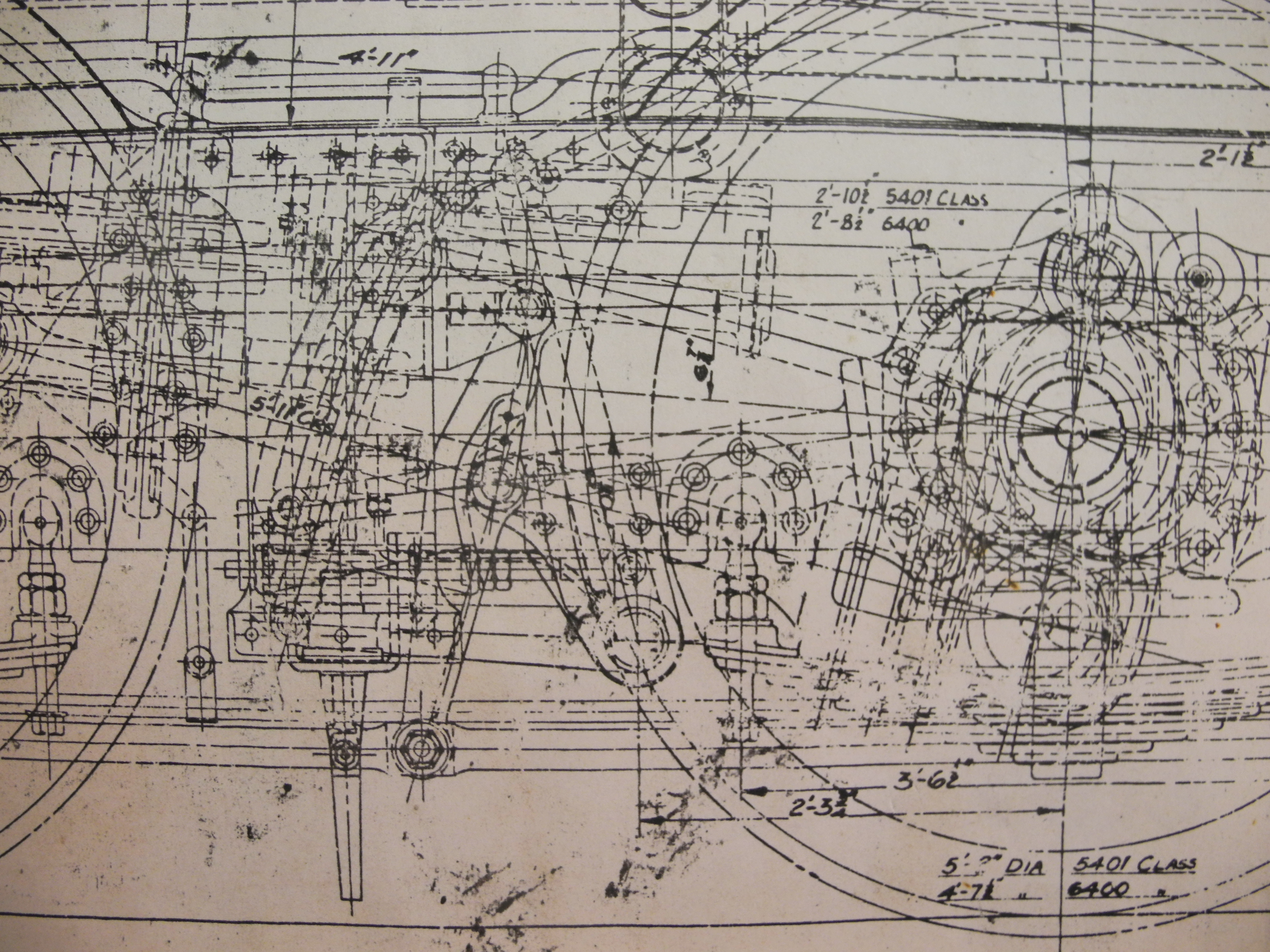
Fig 31 - Part of GWR drawing
The way you choose to use 2D CAD is of course, up to you. There is no 'One True Way', but if you're new to CAD, try not to limit your horizons by thinking of it just as a replacement for paper and pencils. You may choose to draw component parts one per sheet, saving each as a separate file. Perfectly good if that's the way you want to work, it's then a simple matter to name files sensibly and arrange larger projects with many parts into some logical, hierarchical arrangement of folders or directories. Alternatively, you may choose to draw all the parts spread out upon the same sheet – unlike paper drawings there is no real limit to the size of your drawing sheet. This is also fine if that's what works for you.
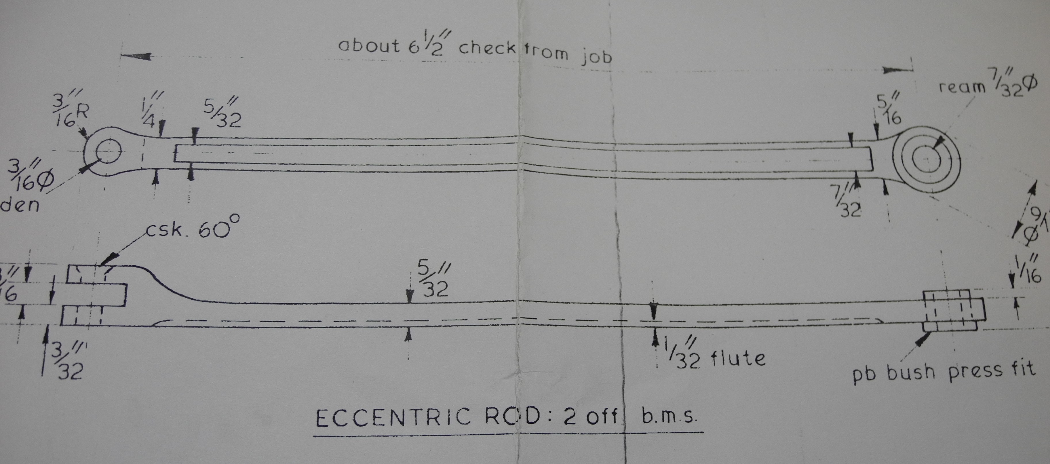
Fig 32 - About sixandahalf DSCN0942 cropped
However, we can probably come up with better ways. By drawing multiple parts as whole assemblies on the same sheet in 2D with components drawn in positions such that they connect as they will in the finished item, it becomes immediately obvious when we draw a connecting rod at the wrong length, or when something that should fit, doesn't. This method also leaves no excuse for any “about this long” dimensions (Fig 32) because by drawing accurately in the first place, we know all the dimensions. There's nothing new in this idea. Fig May01 shows part of a Great Western Railway drawing dated 1931. This almost X-ray-like side view of a locomotive makes more sense when viewed in conjunction with the similarly detailed plan view (not shown). 2D CAD has the advantage of offering many layers which can be switched on and off at will, making it far easier to see just as much detail as we might want.
Fig 33 - Springbok early stages
Fig 33 shows a start having been made re-drawing a locomotive design using AutoCAD LT. Note the 'Layers' pull-down menu showing details of some of the layers used. Using a new layer for each new component, or group of components, is a good idea. Turning on all the layers in a complex design can give a congested view that's difficult to follow, similar to the GWR example of Fig 31, so it makes sense to find out how to create and use new layers, how to change the colours and give them sensible names, and to use a lot of them. Most layers are turned on in this view from early on in the project, probably all except the layer named 'Dimensions'. The boiler has been drawn on a layer named 'Boiler', the loco frames on a layer named 'Frame' and so on. Already clear to see is one of the infamous 'errors' we're trying to trap out of this vintage design, note the square hole in the frame for the boiler blow-down valve. It's too low!
Also shown in Fig 33, the cylinder, piston, valve and parts of the motion being drawn away from the loco frames, “down on the floor”, so to speak. The intention here was to get this whole sub-assembly sorted out in a horizontal orientation prior to lifting and tilting into position on the loco. Likewise the coupling rods waiting to be lifted (and tilted) into position.
Fig 34 shows part of the same design a little further on, the cylinder and motion assembly has been 'lifted' and tilted into position, and this time DraftSight 2D CAD software is in use. Next some time was spent looking at ways of making the build easier and better. Several design changes were made.
CAD Aids Design Improvement
Fig 34 - Springbok later detail
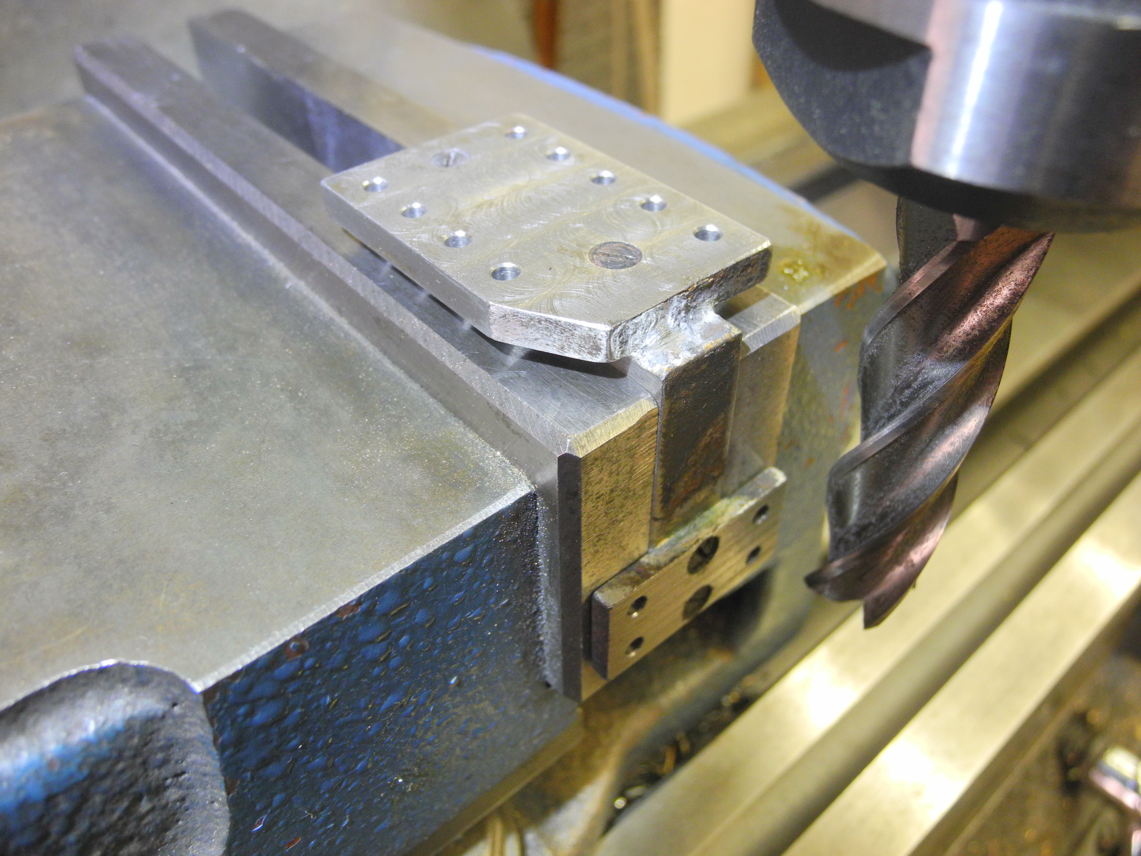
On the original drawings the Motion Plate assemblies are shown bolted to the frames vertically, using frame holes in two vertical columns. A problem with this is in angling the foot joining to the slide bars, to the correct angle. Easier and quicker would be to make the motion plate assemblies square, and mount it onto the frame at the slight tilt. By drawing this as part of the greater cylinder assembly and drawing it square to the slide bars, this tilt has been automatically incorporated when the whole cylinder assembly was 'lifted and tilted' into position, the correct hole positions being defined in the process. Figs May05 and May06 show a finished motion plate assembly, bolted to the frame and supporting the slide bars (it all fits!). These are fabricated from three pieces of steel, the main centre part to which two flat plates are silver soldered. After soldering, the assembly was mounted on the mill as shown in Fig May07. Using a long end mill as shown, the foot was machined just sufficiently to clean off to a flat surface, and the machine DRO was noted. Next, the frame bolting surface was machined, again just sufficiently to reveal a clean, flat surface. Finally the holes were drilled in the frame bolting face using the noted DRO reading as reference, and using the DRO to get holes in exactly the intended positions. (For this job 'HNC' was deemed quicker than 'CNC'.) By these means, we have ensured the foot and the frame plates are exactly at right angles, the lines of the mounting holes are perpendicular to the foot, and the foot will be at the correct height below the mounting holes.
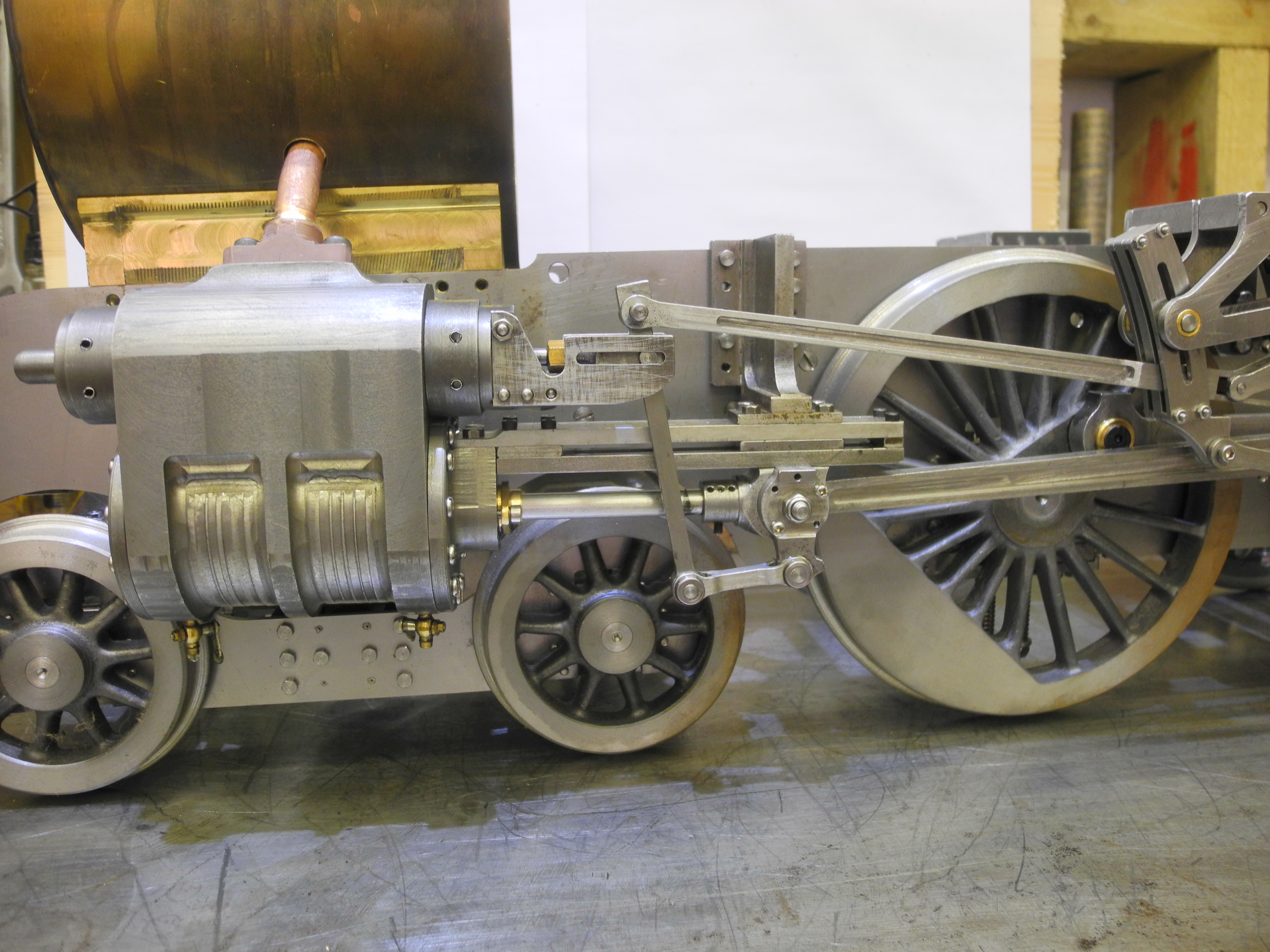
Fig 35 – Photo of Springbok
Having redrawn most of the engine using 2D CAD, several other changes suggested themselves. The cylinders looked too long such that bogie wheels would clout the cylinder covers on even gentle curves. The pistons also appeared far thicker than they needed to be, these were thinned and the cylinders shortened by a quarter of an inch. This improved the prospect of the finished loco negotiating typical club track curves (other builders have lengthened the bogie wheelbase).
Fig 36 – Motion Plate Closeup
Checking some geometry revealed that, as originally drawn, the connecting rod would clout the end of the slide bars. This problem was eased by noting the piston rod was longer than it needed to be. Shortening this enabled moving the slide bars forward again and shortening them also. By now the con-rod had stretched almost 0.4 inch so reducing the angle of its swing, these measures between them just eliminating the 'clout'. These changes cause the anchor link to shorten, the radius rod to lengthen and therefore, the radius of the expansion link slot to increase … the beauty of CAD compared to paper, is that you can go back and make as many changes as you like. After all the tweaking, shifting and (hopefully) improving was completed, all the frame hole sizes and positions are finally confirmed.
Fig 37 – Motion Plate Machining
Lists and Pointers, ##123 ; What's This ?
In a previous edition readers were left to consider the meaning in Mach3 G code of '##number', with the promise that this was “potentially enormously useful”. It certainly came in handy for drilling lots of holes.
Mach3 G code makes available some computer memory locations for storage of 'parameters'. These locations are accessed using the '#' symbol and locations are numbered from one up to some thousands (check Mach3 documentation for details), and '#n' is a reference to memory at location 'n'. Faced with creating a programme to drill many holes, we could use a style:
G0 X 9.2 Y 23.5 ; move to position of first hole
M98 … subroutine or 'canned cycle' to drill a hole
G0 X 9.2 Y 27.5 ; move to position of second hole
M98 … subroutine or 'canned cycle' to drill a hole
… etc.
This is tedious, inelegant and hard to follow. Another method would be to create a more readable list or table of XY hole coordinates and write a programme to work through the list. Here is the start of such a table, using parameter cells numbered 200 and up:
;	Hole Table
#200 = 9.2	 #201 = 23.5
     ; X and Y coords of first hole
#202 = 9.2	 #203 = 27.5
     ; X and Y coords of second hole
… etc.
The hole drilling programme will need to 'point to' the list in order to read coordinates from it. Let us say, for example, the memory at location 50 is used to store the 'pointer'. To set-up the pointer:
#50 = 200 ; pointer initialised to 'point to' #200
Reading this back, #50 will return '200'.
Similarly, reading ##50 will return the figure stored in location #200, which in this example is 9.2, the X coordinate of the first hole.
Then in a loop, successive hole positions may be read:
…
G0 X##50 Y#[1 + #50] ; move to next hole position
; Drill hole here
#50 = [2 + #50] ; Set pointer to Point to next hole
; Repeat loop
This idea becomes more useful still when many holes of various sizes are called for. It may be sensible to start all holes using a centre drill. In this case, the centre drill is fitted, the programme is 'pointed to' the top of the list and a 'length' parameter set to the total number of holes. But the list may be ordered so that the first few holes are to be 'size one', the next block 'size two' and so on. The same drilling programme and list can be used by setting the 'pointer' to the start of the wanted sub-section with the 'length' set to the number of holes of that size. Stops for tool changes are easily implemented in code. Using the form:
M6 (msg:Stopped. Change drill to No34. Reset Z)
M6 stops the machine, the comments in the '()' parentheses will be displayed in the Mach3 'Status' window. After changing and resetting height as needed, clicking on the 'Start' button causes resumption of the programme, M3 will need to follow M6 as 'Start' does not restart the spindle.
This concludes our study of Mach3 G code programming, and along the way methods for packing a lot of functionality into a little code have been shown. Working like this imparts a quicker and deeper understanding of the CNC machine and its characteristics than working with 'higher level' programmes such as Vectric V Carve and other CAM solutions from the start. There are many way of working more productively using other software, with or without Mach3.
Finally, Drilling Frame Holes
Having created a table of hole positions, frames were then drilled using the KX3 CNC mill driven by Mach3 software. This proved a pain because the frames are so long that four separate set-ups and CNC files were needed. It would have been quicker to use HNC methods on the larger manual mill available, although even this would have required at least two set-ups. Better still might have been to send the drawing file to the laser cutting people who could have cut out the frames and drilled all the holes to the drawing at a cost. Time could probably also have been saved by finding CAM software to read the DXF or DWG file and extracting a drill programme for us!
Having invested time in analysing and improving the design, attention turned to valve setting – about which much has been written! The established method for this design includes making customised eccentric rods to a length determined by the results of some time consuming experiment and measurement (Fig 32). Understandable from the days when everything was marked out by hand, this method provided an opportunity to cancel-out some of the cumulative measurement errors in some other parts. However, by using CAD and H/CNC methods, it becomes possible and sensible to make everything to the correct size (within realistic 'steam engine' tolerances) in the first place – because we can!
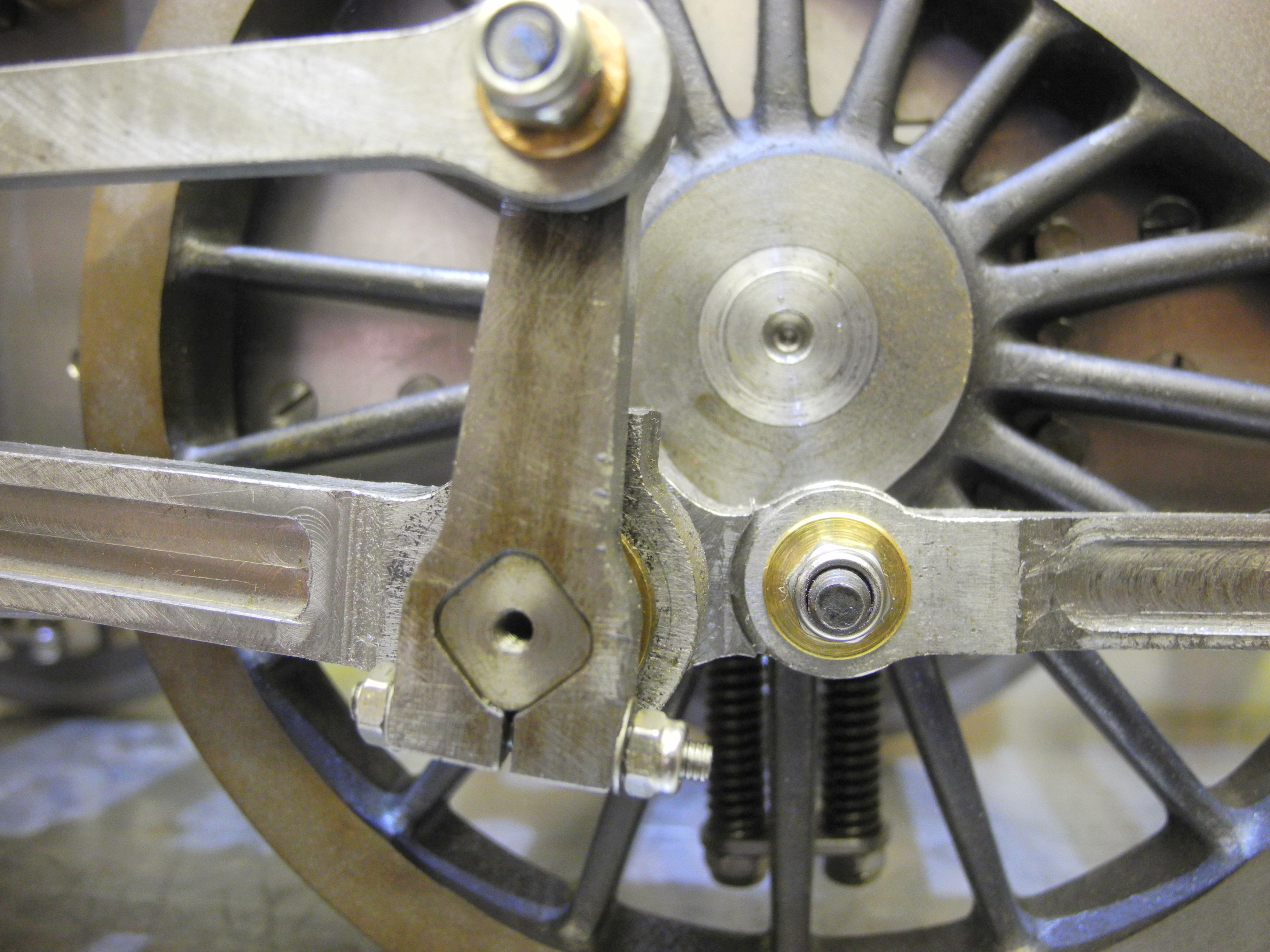
Fig 38 – Return Crank Closeup
The return cranks may also be set at the known correct angle at the outset, so avoiding another hit and miss factor in setting up. Fig 38 illustrates a method. A G Code programme was created to machine squares with rounded corners. An internal square cut using round cutters will, obviously, have rounded corners. The return cranks were CNC machined from flat stock, first to machine the round-cornered square hole (the first stage was to drill a round hole at each corner). The profile was then cut, liberating the return crank from stock material. The crank pin blanks were mounted on the CNC mill in a three jaw chuck mounted pointing up. The round cornered squares were then machined, the final size being obtained by the slight tweak of a number in the G Code file until a snug fit was obtained.
Finally, the crank pin return crank assembly was fitted to the wheel using Loctite, the correct angle being assured by use of a simple jig setting the crank pin the right distance from the axle centre.
Having made the valve spindles to the length measured from the CAD drawing, there was nothing left to set-up in the motion or the valve gear. It runs nicely on air, but the real test run on steam at the club track, that's still some way off.