Turning now to the creation of programmes that Mach3 CNC software can use to simulate the machining of items. Mach3 software is an excellent learning tool, aspiring CNC machinists would be well advised to spend time learning with simulations before letting themselves loose on real CNC machines. Mistakes made in simulation do not result in personal injury or expensive machine damage!
Sketch, CAD, or CAD/CAM for CNC
An engineer using tools and machines to make something will most likely be working to a sketch or drawing. Whether a 'fag packet' sketch or something produced to a higher standard using a computer aided design (CAD) system, a certain skill and effort is involved in conveying design information from the drawing to the CNC machine programme. Different tasks suggest different methods of design information transfer, but the end result will be a G code programme listing to be loaded into Mach3 which will then, all being well, enable CNC machining to be simulated or carried out. After a little practice, many everyday engineering tasks can be programmed directly in hand-crafted G code without much effort. Drilling rows of holes or holes around a circle, machining regular polygons, profiling some clock or steam engine parts from sheet material, these are examples that lend themselves readily to hand-crafted code typed straight into the text editor. A CAD drawing may be useful as confirmed accurate X and Y coordinates may be read directly from the CAD screen and transferred into lines of G code (although prone to human error). More complex work such as that involving text engraving or any decorative or irregular artwork is probably better handled using some CAD/CAM system – it's difficult to imagine any reason to embark on creating scalable text fonts in G code!
One school of thought says that as many tasks are not practical without CAD/CAM, you may as well use CAD/CAM for every task. As for CAD drawing systems, several good 'AutoCAD lookalike' packages are freely downloadable from the internet, so it makes sense to use one. Using CAD is a particularly good idea for builders of steam locos or anyone who works to old drawings. Redrawing on CAD will help pick up on most of those famous 'errors', and saving files in more than one 'industry standard' formats (DXF, DWG etc) helps ensure your saved work will still be usable into the future after those all too frequent computer and software upgrades. A considerable range of CAD/CAM software systems are available, as any web search will reveal. At the time of writing relatively few are likely to suit the pocket of the hobbyist, but products found at www.vectric.com deserve a look, 'Cut 2D' making a good, affordable intro to CAD/CAM.
Using CAD/CAM as an excuse to ignore and step over G code, while tempting, is probably not the best strategy. Mach3 only accepts G code files, and there may be times when CAD/CAM produces something that almost does what you want, being able to read the G code it produced for you may then give the clue you need to fix any problem.
How to Hand-Craft G Code
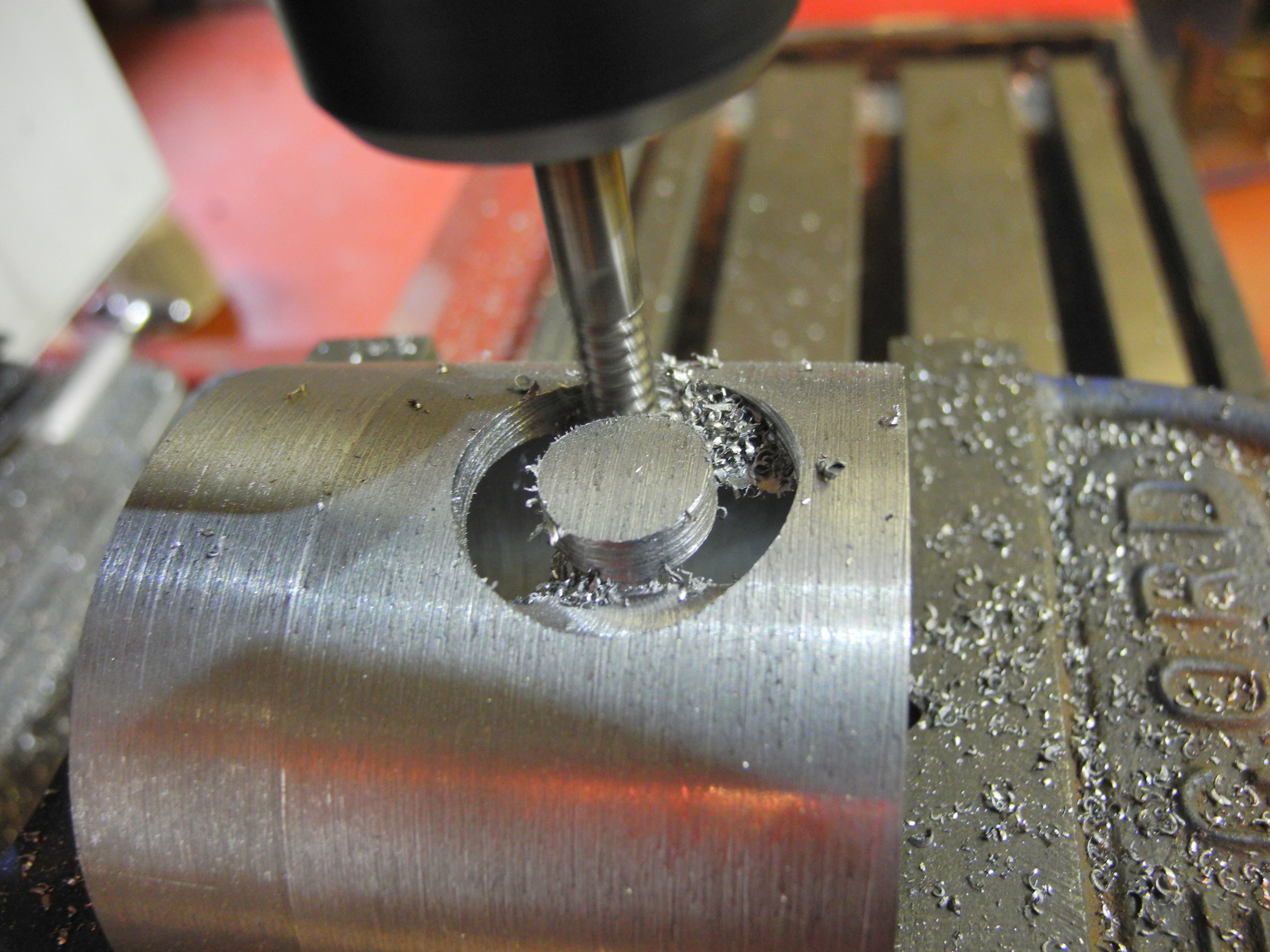
Fig 301 - Small milling cutter makes large hole
Some programming languages take years to learn because they are huge. Others are small, G code is very small. Some languages are complex, others are simple, G code is very simple. Being very small and very simple, very little time need be spent learning about G code before the budding CNC machinist is capable of producing useful work – it will be time well spent. The survival of G code to the present day stems from the fact that any practical shape is machined using cutting movements in straight lines and arcs, and that's it. Complex curves and any intricate shapes are only constructed using sequences of arcs and straight lines. The requirements are that simple, and that's what G code was designed for.
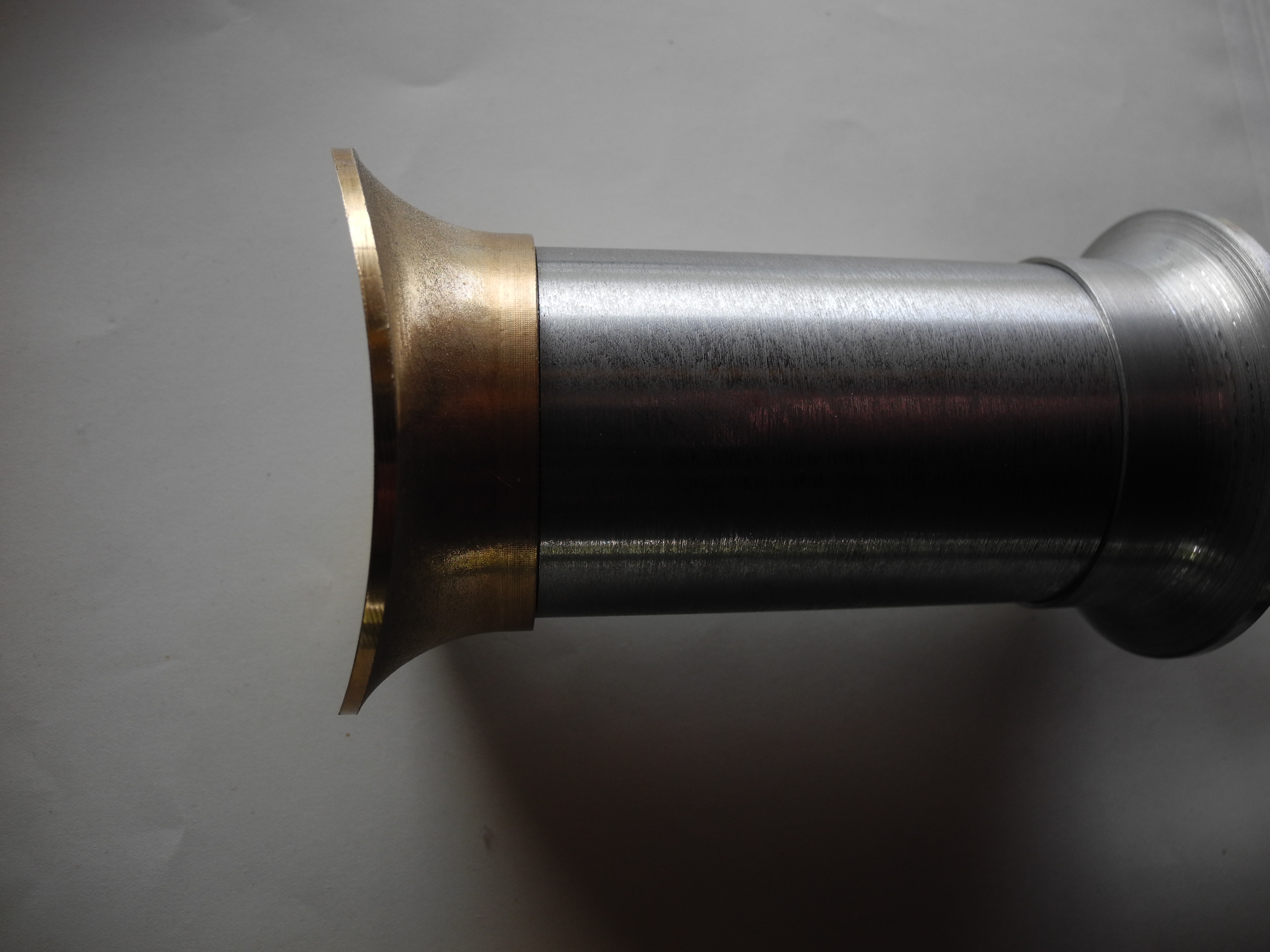
Fig 302 - Chimney Base
Using a milling machine with three axis control in the examples here, G code provides the simple ability to make movements in a straight line from any point in the three dimensional working envelope of the machine, to any other point - straight lines in any direction. Arcs are simple to programme in any of three planes; XY, XZ or YZ. Arcs at other angles are possible but require thought and programming effort.
Being so ancient, G code, as a language, is 'feature poor'. This will become apparent when we find ourselves muttering “if only it would let us ...”. However, as a suggested first task in learning G code, creation of a programme template file is a worthwhile exercise. This can then be used as the starting point for all future programmes and should be written to encourage a structured approach, and contain all the set-up 'preamble' codes to put a machine into a known, safe state, and codes to stop and end the programme safely. With this in place, programming effort may then be put into the creation of a collection, a library, of useful sub-programme module files, which may then be cut-and-pasted together to provide a multitude of machining possibilities. As an example, code will be worked up to produce a programme which cuts an any-sized hole to any practical depth, as used for cutting holes in sheets, tubes, boiler barrels and the like. This programme is shown running in Fig 301. Further examples will then lead on to show the power of linking reusable modules to produce complex machining sequences. G code may be simple, but as will be shown, safe, reusable, modular programme design enables us to produce some quite complex machining operations with amazing ease and speed.
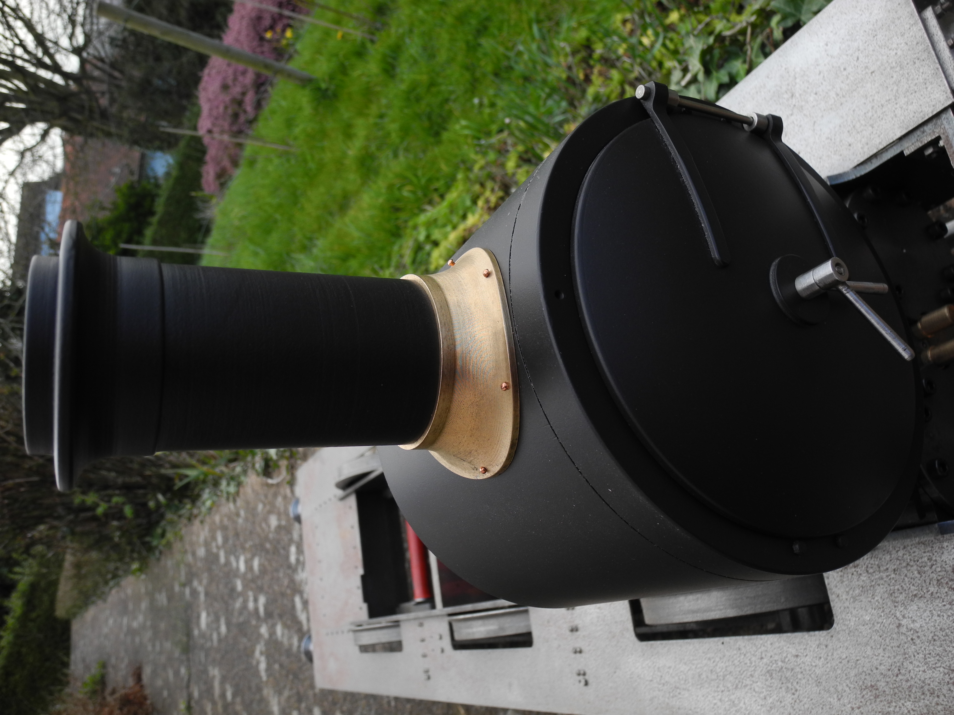
Fig 303 - Completed Chimney mounted on smokebox
As one example, the locomotive chimney base shown in Figs 302 and 303. This used two separate hand-crafted G code programmes to machine completely, one a little involved but nevertheless still using only about one hundred lines of code to machine the upper surface, blending the profile hugging flange up to the circular section at the bottom of the chimney straight section, and another quite straightforward programme to mill out the arc profiled underside to sit snugly upon the smokebox. Machining a chimney base shape such as this is a challenge for any engineer, and a couple of brave and commendable examples of doing this the hard way, using manual methods, have been seen in the model engineering press in recent times. In contrast, this CNC machined example used only two small milling cutters, and the machine set-up simply involved holding the work on a three jaw chuck mounted flat on its back on the KX3 CNC mill table.
However, the main emphasis here will be on developing a sound approach to the efficient creation of safe, useful, robust, manageable programmes. This will not be a Mach3 or G code tutorial, enough of which may be found in the excellent Mach3 documentation and elsewhere. That said, this series of articles provides sufficient information for the up-coming CNC machinist to produce work to the level shown in these examples and beyond. The art is to discover how to do great things with a little G code. This is not quite the same as learning all about G code. Although there is not that much to G code to start with, there are features you may never have the need to use, as well as features you may choose not to use. A G code output file from a CAD/CAM is often a very long list of a very few G codes used many times.
Making a start with Mach3 CNC Software
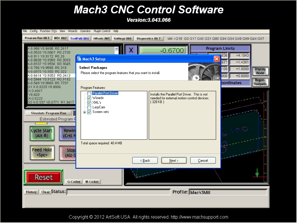
Fig 304 - One of the Mach3 Install screens
Mach3 will work on most PC computers running one of a variety of versions of 'Microsoft Windows' operating system. Not all PCs are capable of also driving external electronics or real CNC machines, details are explained in the Mach3 documentation, however very few problems have been seen when using Mach3 in 'simulation' only mode, as here, with 'Windows' versions up to and including '8'.
While learning to create CNC programmes for Mach3, most time will be spent using a simple text editor, such as 'Notepad' or similar, to create and modify programme files. The file is then loaded into Mach3 to see what happens.
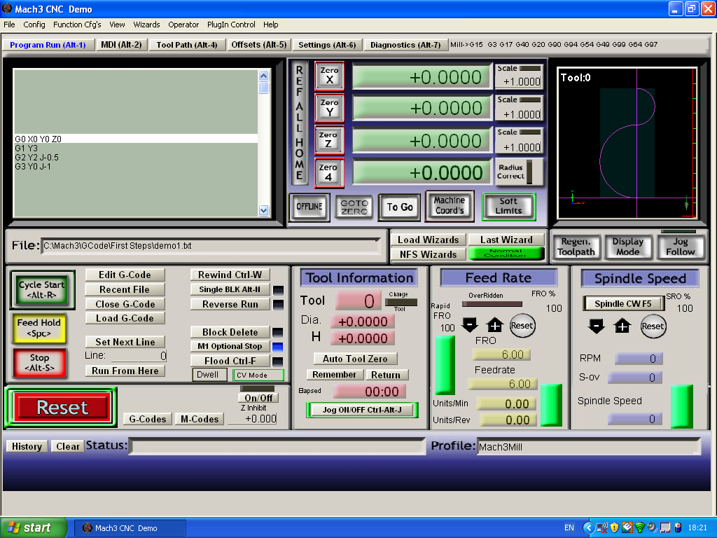
Fig 305 - Mach3 Programme Run screen with code fragment
Full instructions for installing Mach3 may be found on the web site www.machsupport.com. Files 'Mach3Mill Install and Config Guide ' and 'Using Mach3Mill ' may be found on the 'Documentation' page. These reference documents should be downloaded (and optionally printed out). When installing Mach3, note the “parallel port driver” is not needed for simulation and is best not installed as installing the driver severely limits file sizes unless a full license is purchased. During installation the screen shown in Fig 304 will be seen. Clicking to clear the 'Parallel Port Driver' and LazyCam' boxes is the preferred option at this point. LazyCam is described as a 'dead project', best not to waste time with that. Should your system eventually be connected to a CNC machine or other external electronics requiring the port driver, it is simple enough to install again later.
The Mach3 install process should have placed a 'Mach3Mill' icon on the PC desktop. Clicking on this starts Mach3 software, and you should see a screen similar to that shown in Fig 305 - This is the main Mach 3 “Programme Run” screen (a small programme fragment has been loaded in this image).
Mach3 starts up in the main 'Programme Run' screen, and the border around the 'Reset' button flashes alternately red and green. Clicking the mouse or pointing device on this button should reset the system, stop the flashing leaving a green surround. The system is now ready for use. At this point, it is a good idea to read the first three sections of the “Mach3Mill_1.84.pdf” document, have a play, and become familiar with some of the features of Mach3.